Start with the System Voltage and Voltage Class
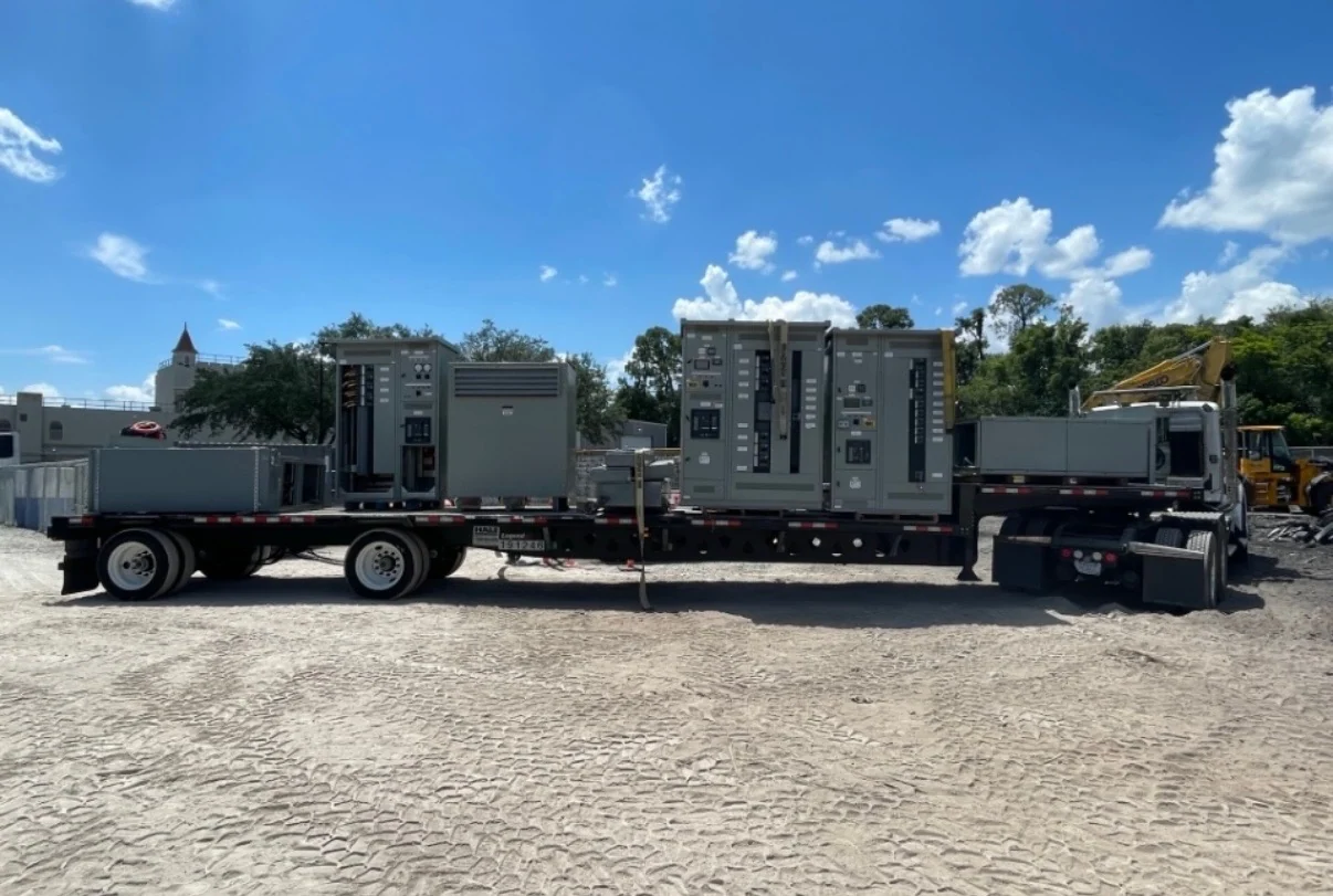
A 27 kV switchgear specification should begin with the electrical system, not with a catalog label. Confirm the nominal line-to-line voltage, maximum operating voltage, frequency, phase arrangement, grounding method, and whether the equipment connects to a utility, transformer, generator, collector circuit, or industrial feeder. The equipment voltage class must provide appropriate margin above normal system voltage, while insulation coordination must reflect the actual installation. A 27 kV distribution system may call for different construction and switching arrangements than a lower-voltage lineup, so the one-line diagram and system study should control the design. Switchgear Builders manufactures new electrical switchgear in the United States, custom to project requirements, with American components and nationwide shipping; the final configuration remains subject to engineering review and project-specific requirements.
Define Grounding and Insulation Requirements
Grounding affects the stress placed on insulation and the way protection detects and clears faults. The design team should identify solid, resistance, reactance, or other grounding arrangements where applicable, along with the expected ground-fault current and clearing time. Specify insulation level, clearances, creepage considerations, cable terminations, and any impulse or environmental requirements that apply to the installation. Outdoor exposure, altitude, contamination, moisture, and temperature can change the equipment interface even when the nominal voltage remains 27 kV. These inputs help determine enclosure details, barriers, bushings, cable compartments, and grounding provisions rather than leaving critical assumptions to fabrication.
Match Interrupting and Short-Circuit Duties
Available fault current must be established at the proposed equipment location before selecting switching and protective devices. Review three-phase and line-to-ground fault calculations, asymmetrical effects where applicable, source contributions, transformer impedance, and the required clearing sequence. Device interrupting capability is not interchangeable with the assembly's short-circuit withstand requirements, so the specification should identify each duty clearly. Also consider momentary or making current, bus bracing, grounding continuity, and the mechanical forces associated with a fault. A qualified engineer should reconcile study results with the selected 27 kV switchgear construction, protective devices, cable terminations, and operating sequence.
Coordinate Feeders, Switching, and Protection
A useful 27 kV distribution design describes what each feeder must do during normal operation and during abnormal conditions. Identify incoming sources, outgoing feeders, transformer connections, bus sections, ties, switches, fuses, circuit breakers, relays, metering, and grounding switches as applicable. Time-current coordination should account for upstream and downstream devices, transformer inrush, motor starting, generator behavior, and the utility or facility protection philosophy. If a tie or alternate source is included, document the permitted operating states and interlocking logic instead of relying on a generic main-tie-main phrase. The manufacturer can build to an approved one-line diagram and control narrative, but settings and protection responsibility must be assigned by the project team.
Plan Enclosure, Access, and Cable Interfaces
Physical planning is as important as the electrical rating for medium-voltage distribution equipment. Provide available room dimensions, lineup orientation, equipment elevation, cable entry direction, termination space, phase spacing needs, ventilation conditions, door swing, maintenance access, lifting path, anchorage, and the location of incoming and outgoing conductors. Specify indoor or outdoor installation and the environmental enclosure requirements supported by the site. Large assemblies may need shipping splits, field joints, removable panels, or defined lifting points, so these details belong in the layout review before release. A practical drawing package should show the relationship between 27 kV switchgear, transformers, cable trenches, grounding conductors, and adjacent equipment.
Prepare a Complete Manufacturer Inquiry
For a custom 27 kV switchgear quote, send the one-line diagram, equipment schedule, system study inputs, voltage and frequency, grounding method, fault duties, feeder count, device preferences, control voltage, metering needs, communication requirements, enclosure location, dimensions, cable data, drawings, inspection expectations, and shipping destination. State which requirements are mandatory and which are design options. Ask the manufacturer to identify assumptions, exclusions, required approvals, documentation, and any project-specific standard or listing question that needs confirmation; UL 891 applicability, if raised by the project, must be evaluated for that particular equipment and configuration. Switchgear Builders supplies new custom-built equipment nationwide, with scope and delivery terms confirmed for each inquiry rather than assumed from a generic product name.