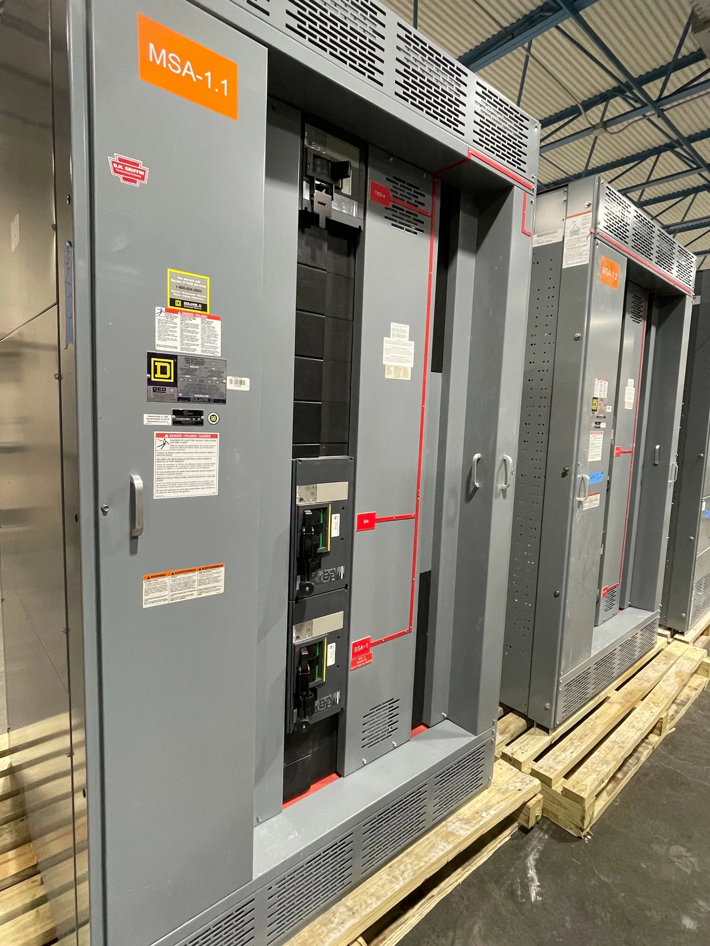
Start with the System Voltage and Voltage Class
A 35 kV switchgear specification should begin with the electrical system, not with a catalog label. Confirm the nominal line-to-line voltage, maximum operating voltage, frequency, phase arrangement, grounding method, and whether the equipment serves a utility, transformer, generator, or distribution feeder interface. The system voltage establishes the context for selecting a suitable equipment voltage class, while insulation coordination and operating conditions determine whether the proposed construction is appropriate. A manufacturer can build new 35 kV distribution equipment to a project-defined specification, using the one-line diagram, load data, utility requirements, and installation conditions as the starting record rather than assuming that every application has identical needs.
Define Feeder Duty and Interrupting Requirements
The phrase 35 kV switchgear does not by itself define the duty of a feeder lineup. The design team should calculate available fault current at the equipment location, identify the interrupting capability required of each switching or protective device, and distinguish momentary, withstand, and interrupting requirements where applicable. Continuous current also matters: normal load, transformer energization, motor contribution, future expansion, and emergency operating conditions can affect device and bus selection. Provide the fault study assumptions, utility contribution, transformer impedance, grounding source, and feeder configuration for review. These inputs let the manufacturer coordinate a new assembly around actual electrical duties instead of relying on an isolated voltage number.
Coordinate Grounding, Insulation, and Clearances
Grounding is a design input with consequences throughout a medium-voltage lineup. Specify whether the system is solidly grounded, resistance grounded, reactance grounded, or configured under another engineered arrangement, and identify how ground-fault current is expected to return. The grounding method influences relay settings, cable terminations, insulation stress, and the selection of grounding conductors and bonds. The specification should also address insulation level, required clearances, creepage, cable entry, phase spacing, and environmental exposure. Those details should be checked against the project standard and the equipment design by qualified electrical professionals; an enclosure that fits a room dimension is not necessarily suitable for its electrical environment.
Plan Protection and Operating Sequences
Protective-device coordination turns a 35 kV distribution concept into an operable system. Gather the time-current curves, transformer data, feeder impedance, downstream device settings, relay functions, instrument-transformer information, and any source or tie operating modes needed for a coordination study. Define normal, alternate, and maintenance states separately, because a bus tie or generator interface can change fault contribution and selectivity. The equipment package should identify control power, trip and close circuits, permissives, interlocks, local indications, remote contacts, and the intended sequence for isolation and restoration. Final settings and logic require engineering review; the manufacturer should build to approved drawings and the documented operating sequence for the project.
Resolve Physical Interfaces Before Fabrication
A useful 35 kV equipment request includes the physical information that determines whether the lineup can be installed and maintained as intended. Provide room drawings, access routes, floor elevations, foundation details, cable trench or conduit locations, termination orientation, bus connections, lifting constraints, ventilation conditions, and required working and maintenance clearances. Identify whether the equipment is indoors or outdoors and describe dust, moisture, corrosive exposure, altitude, seismic design criteria, and ambient temperature when those factors apply. Switchgear Builders manufactures new custom switchgear in the United States with American components and can coordinate the requested enclosure, interfaces, documentation, and nationwide shipping around the approved project scope.
Build a Complete Submittal and Verification Plan
Before ordering new 35 kV distribution equipment, align the one-line diagram, equipment schedule, elementary diagrams, wiring diagrams, nameplate data, device information, cable and termination schedule, and installation responsibilities. State which inspections, continuity checks, insulation checks, functional demonstrations, and other electrical tests are required, along with acceptance criteria and record formats. If the project references a standard such as UL 891, first confirm whether that standard applies to the specific equipment type and project, then establish any applicable listing, construction, or verification requirements with the responsible parties; do not assume the reference creates a blanket listing. Clear documents reduce redesign risk and give the manufacturer, engineer, contractor, and owner a shared basis for review.