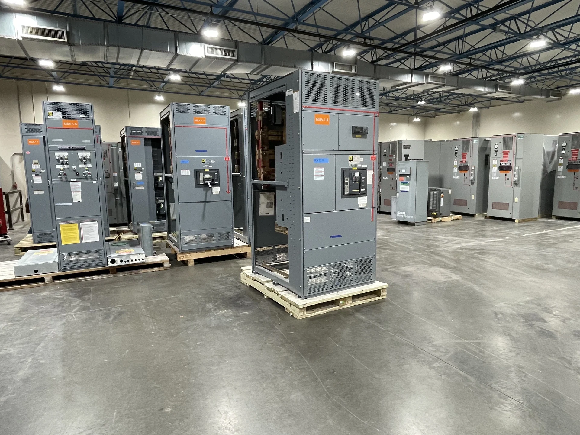
Start with the Actual 277/480 V System Arrangement
277/480 V switchgear commonly describes a three-phase, four-wire distribution system in which 480 V is available phase-to-phase and 277 V is available phase-to-neutral, where the transformer, grounding arrangement, and project design support those relationships. The nominal label alone is not enough to release equipment for fabrication. Confirm the system frequency, phase sequence, number of wires, neutral treatment, grounding method, service or feeder function, and whether the equipment connects to a separately derived source. A current one-line diagram, utility information where applicable, and the engineer's design basis give a manufacturer the context needed to build the correct distribution assembly rather than interpreting a voltage phrase in isolation.
Define Current, Fault Duty, and Device Ratings
A useful 277/480 V switchgear specification separates continuous current from short-circuit duty. Identify calculated demand, main and feeder currents, bus current, available fault current at the equipment terminals, and the interrupting capability required of each protective device. Consider transformer impedance, generator contribution, motor contribution, utility changes, and downstream coordination inputs when an engineer establishes the fault study. Future load growth may affect bus space or feeder provisions, but it should not be treated as a substitute for an engineered rating. The manufacturer can build custom equipment to the approved ratings and device schedule, using American components as specified for the project, without assuming a rating from the nominal voltage alone.
Coordinate Protection Across the Distribution System
Protective-device coordination is where a voltage specification becomes an operating scheme. Provide time-current study information, preferred breaker or switch functions, trip-unit requirements, ground-fault provisions where applicable, and the intended selective-coordination objectives. Main, tie, and feeder devices must be considered together with upstream transformer protection and downstream loads; a device that fits the enclosure may still be unsuitable for the planned sequence or available fault current. For a custom build, document normal source paths, alternate sources, tie operation, interlocks, controls, metering, and any remote signals on the drawings. Final settings remain an engineering responsibility and should be reviewed before commissioning.
Plan the Neutral, Grounding, and Phase Interfaces
The neutral and grounding details deserve explicit treatment in a 277/480 V lineup because line-to-neutral lighting loads may share a distribution system with three-phase motors and other line-to-line loads. State whether a full-size neutral, reduced neutral, switched neutral, or no neutral is appropriate for the defined loads, and identify the bonding point and grounding-electrode or equipment-grounding interfaces required by the design. Show incoming and outgoing conductor sizes, lug arrangements, cable entry direction, ground bus expectations, and any metering connections. These details affect compartment space, termination access, and field installation, so they should appear in approved drawings rather than being left to assumption.
Resolve Enclosure, Room, and Installation Constraints
Electrical performance is only one part of specifying 277/480 V distribution equipment. Supply the intended indoor or outdoor setting, environmental exposure, enclosure requirements, available room dimensions, working clearances, access route, floor or support conditions, cable bending space, and maintenance approach. Identify whether the lineup must be split for transport, how sections will be handled, and where lifting or anchorage provisions are needed. Door swing, removable-device withdrawal space, top or bottom entry, ventilation, and adjacent equipment can change the practical footprint. A manufacturer can coordinate enclosure layout and shipping sections to the approved project information, while the engineer and installer confirm site clearances and field responsibilities.
Prepare a Complete Manufacturer Quote Package
For a meaningful quote on new 277/480 V switchgear, send the one-line diagram, equipment schedule, load or feeder list, fault-current study, coordination requirements, physical dimensions, enclosure environment, utility or service-interface criteria, control schematics, metering needs, and required drawing or test documentation. Include the project destination because shipment planning depends on section dimensions, weights, access, packaging, and freight arrangements. Switchgear Builders manufactures custom electrical switchgear in the United States, supplies American components, and ships nationwide; project-specific component selection, documentation, construction details, and shipment terms should be confirmed in the quotation and approved submittals. UL 891 applicability, if relevant, must also be confirmed for the particular project rather than assumed from the voltage class.