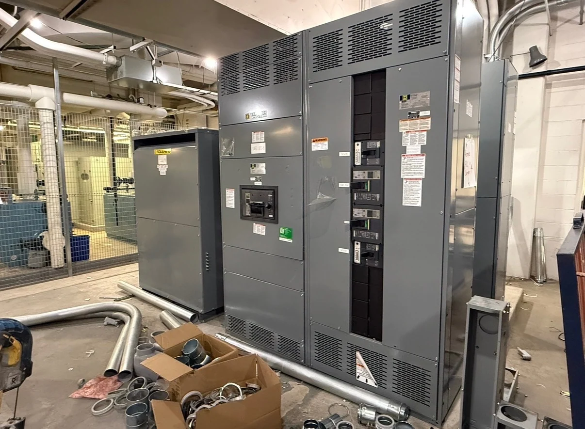
Start with the Equipment Envelope
A switchgear footprint is more than the lineup length printed on a plan. Define overall width, height, depth, section joints, doors, removable panels, cable compartments, and any projections that affect adjacent equipment. The equipment envelope should also account for shipping splits and the space required to align sections during installation. For a useful switchgear specification, identify nominal system voltage, continuous current, short-circuit duty, incoming and outgoing cable arrangements, device positions, metering, and control compartments before dimensions are treated as final. Switchgear Builders manufactures new electrical switchgear in the United States, custom to project requirements, with American components and nationwide shipping; the final dimensional package remains dependent on the approved design and site information.
Separate Working Space from Equipment Size
Working clearance is the accessible area in front of, beside, or behind equipment where inspection, operation, testing, and maintenance activities may occur. It is not simply an extension of the cabinet footprint, and it cannot be inferred from a generic room layout. Coordinate the planned equipment with the applicable electrical requirements, project specifications, and the authority having jurisdiction. Review door swing, handle positions, breaker withdrawal paths, access to terminals, and the location of energized parts as the design develops. A compact lineup may fit on paper yet create an impractical service path if doors open into another lineup, a wall, a structural element, or a required passage.
Map the Movement Path
The route from the receiving point to the electrical room deserves the same attention as the final installation position. Record doorway widths and heights, corridor turns, elevator dimensions and capacity, floor transitions, ramps, overhead obstructions, and any temporary openings required for handling. Confirm whether the lineup will arrive as one assembly or multiple shipping sections, then relate each section's dimensions and weight to the planned handling method. The route should also accommodate protective packaging, lifting equipment, and safe staging without blocking emergency access. Early route drawings and photographs give the manufacturer practical information for enclosure segmentation, lifting provisions, packaging, and shipping coordination without assuming site conditions.
Coordinate Cable and Conduit Interfaces
Cable entry and termination choices can change the usable footprint even when the cabinet dimensions stay constant. Identify top, bottom, or side entry; conductor bend space; termination orientation; conduit locations; ground conductors; neutral arrangements; and whether feeder sections require rear or front access. Compare those interfaces with sleeves, housekeeping pads, trenches, embedded steel, and nearby transformers or busway. Account for bend-radius requirements from the cable manufacturer and the installer’s method rather than reserving an arbitrary void. A dimensioned plan, elevation, and cable schedule should show where conductors arrive and how installers will reach terminations without removing unrelated equipment or compromising required access.
Plan Operation and Maintenance Access
A workable layout lets qualified personnel operate devices, read labels, perform project-defined tests, and remove serviceable components without creating conflicts with walls or neighboring assemblies. Review the direction of door travel, the clearance for a drawout mechanism where applicable, access to fuses or control terminals, and the space needed for test instruments and temporary barriers. Consider future component access and the sequence for isolating equipment according to the project operating procedure. Do not reduce required working space to gain storage or passage area. The electrical engineer, installer, owner, and manufacturer should reconcile layout drawings with field responsibilities before dimensions are released for fabrication.
Release a Dimensioned Submittal Package
Before ordering new switchgear, assemble a coordinated package that includes the room plan, equipment elevations, one-line diagram, section arrangement, cable-entry details, grounding points, shipping splits, weights, lifting information, and identified access zones. Mark fixed architectural references such as walls, columns, doors, finished-floor elevations, and equipment pads. Have responsible project parties review conflicts between the electrical layout and structural, mechanical, fire-protection, and construction plans. Switchgear Builders can use the approved scope to prepare custom equipment and coordinate nationwide shipment, while the customer’s project team confirms field dimensions, installation means, local requirements, and final acceptance criteria.