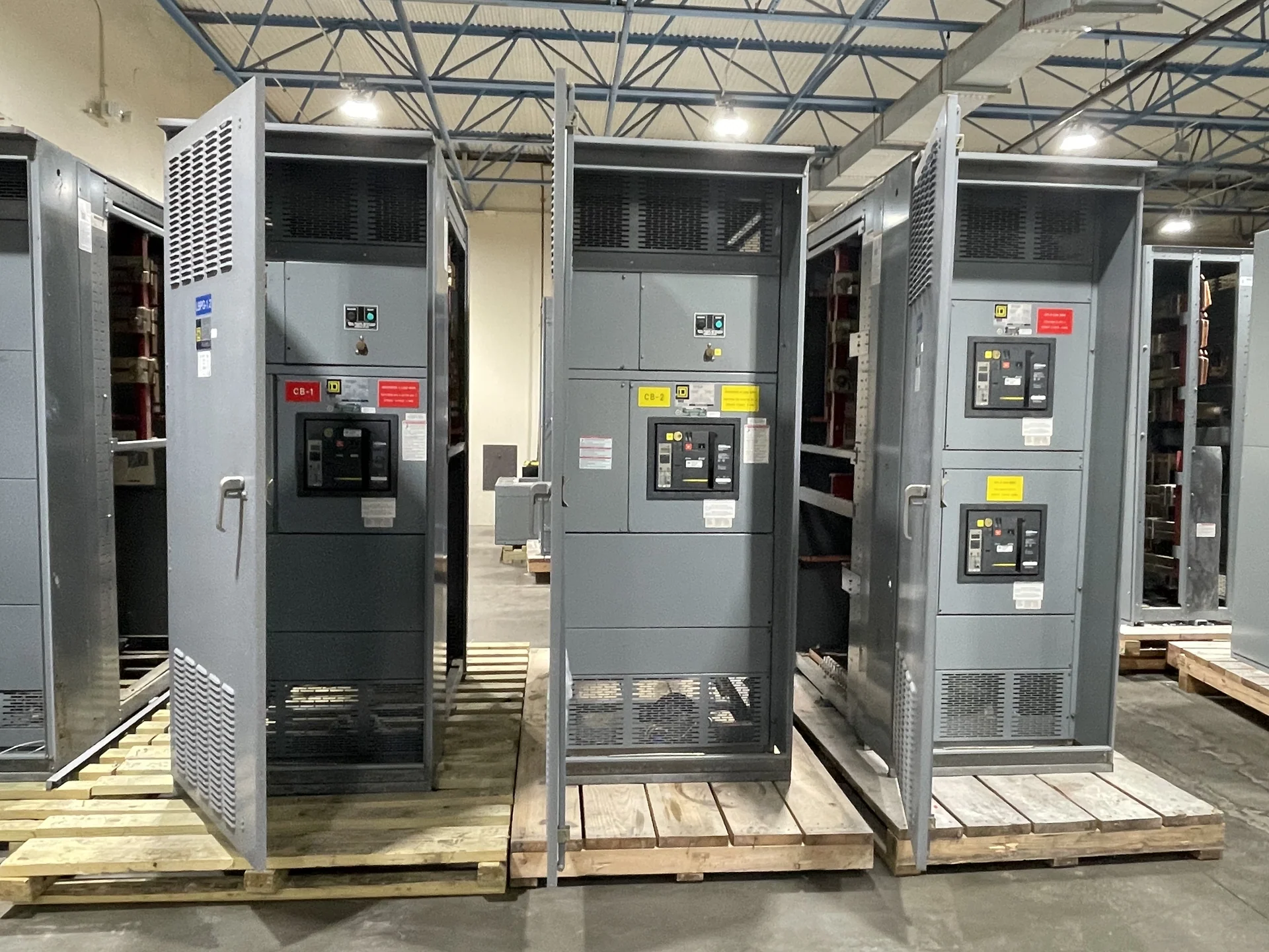
Start With the System Nominal Voltage
A switchgear voltage class selection begins with the electrical system, not with a product label. Gather the nominal line-to-line voltage, phase arrangement, frequency, number of wires, grounding method, and whether the equipment connects to a utility service, transformer secondary, generator, or another source. Nominal voltage describes the system's intended operating level; it does not by itself establish the complete equipment rating. A project may use a familiar distribution voltage while still requiring a different equipment class because of insulation coordination, switching duty, fault exposure, or the physical arrangement of the installation. This distinction keeps a switchgear specification grounded in the actual one-line diagram.
Nominal Voltage and Equipment Class Are Different
Equipment voltage class is the design category selected for the switchgear assembly and its associated devices, clearances, insulation, and interfaces. It must be suitable for the system voltage and the conditions that can appear during operation, switching, or a fault. Do not treat a nominal value such as 480 V or 15 kV as a complete ordering description. The design team should confirm the applicable maximum system voltage, grounding conditions, insulation requirements, phase-to-phase and phase-to-ground relationships, and the ratings of breakers, switches, bus, and terminations. Those inputs allow an American manufacturer to develop custom new switchgear to the project's electrical and physical requirements rather than matching a number in isolation.
Inputs That Shape a Correct Selection
A useful switchgear specification combines voltage information with current and fault-duty data. Provide calculated continuous load, main and feeder currents, available fault current at the equipment location, required interrupting or withstand duties, source contribution assumptions, and protective-device coordination information when available. Add enclosure environment, indoor or outdoor placement, altitude or temperature conditions that affect the design, cable entry direction, equipment dimensions, working clearances, and maintenance access. If the lineup includes metering, controls, a bus tie, transfer functions, or multiple sources, show those relationships on the one-line diagram. A manufacturer can then review the complete electrical context before preparing a custom configuration and quote.
Coordinate Devices, Insulation, and Interfaces
Voltage class selection also reaches beyond the enclosure. Circuit breakers, fuses, switches, instrument transformers, surge protection, meters, control power, cable terminations, and bus connections must be compatible with the selected system and equipment conditions. Review how each device is applied, including its voltage, current, interrupting, insulation, and control requirements, rather than assuming that components share one generic rating. Confirm source and feeder interfaces with the electrical engineer, utility, transformer designer, and installation team as applicable. If the project calls for a particular standard or a UL 891 evaluation, identify that requirement early; applicability and any project-specific listing or capability must be confirmed for the specific assembly.
Build the Specification Around the Project
The final inquiry should state what the equipment must accomplish and how it will connect to the facility. Include the latest one-line diagram, load schedule, fault study inputs, site and room drawings, source sequence, protection philosophy, control narrative, utility metering requirements, cable information, and desired documentation. Ask for clarification where the drawings conflict instead of allowing an unstated assumption to become a manufacturing detail. Switchgear Builders manufactures new electrical switchgear in the United States, builds custom to specification, uses American components, and supplies equipment with nationwide shipping. Project-specific engineering review remains necessary to confirm the requested voltage class, configuration, components, and applicable requirements.
Review the Submittal Before Fabrication
Before fabrication begins, compare the proposed voltage class and equipment schedule against the approved one-line diagram and installation conditions. Check every main, tie, feeder, bus section, device, termination, control circuit, meter, and nameplate description for consistency. Verify dimensions, cable space, access, lifting or shipping splits, grounding and bonding details, and the operating sequence. A disciplined review can reveal a mismatch between nominal system voltage and the selected equipment category while changes are still practical. Request the manufacturer’s project drawings and component data needed for review, then document any engineering or utility comments before the new lineup is released for production and shipment.