Start with the Distribution Arrangement
Switchgear busbar integration begins with the electrical arrangement, not with a generic bar size or enclosure drawing. The project team should establish source locations, bus sections, mains, ties, feeder exits, phase sequence, neutral treatment, grounding connections, and the intended operating sequence. A single-line diagram, load information, available fault current, system voltage, frequency, and continuous-current requirements give the manufacturer a usable design basis. Switchgear Builders manufactures new custom electrical switchgear in the United States, building each assembly around the approved project inputs and supplying it with American components as specified for the equipment package.
Coordinate Busbars, Joints, and Connections
Busbar integration requires careful attention to joints because every connection affects electrical continuity, mechanical fit, inspection access, and installation sequence. Design review should identify where bars join shipping sections, connect to circuit breakers or switches, transition between compartments, or terminate at field cables and busway. Joint hardware, contact surfaces, plating or treatment, torque information, and access for assembly should be defined in the project documentation rather than assumed. A coordinated layout also reduces the risk that a door, barrier, cable lug, or removable device obstructs a connection that must be installed or checked in the field.
Design Supports for Mechanical Duty
Bus supports hold conductors in their intended position and help an assembly address the mechanical forces associated with its specified electrical duty. Their spacing, material, mounting method, phase arrangement, and relationship to joints should be reviewed with the applicable design requirements and the assembly's specified short-circuit withstand expectations. Supports also need to coexist with barriers, shutters, wireways, and service access without creating sharp edges or unnecessary stress on conductors. The final arrangement should be checked against enclosure dimensions, lifting or shipping splits, and the installer’s method for making field connections.
Manage Insulation and Electrical Clearances
Insulation and electrical clearances are project-specific design controls that must be evaluated for the system voltage, equipment construction, environment, and applicable requirements. Review air paths, creepage paths, phase-to-phase spacing, phase-to-ground spacing, barriers, sleeves, boots, and protected transitions wherever conductors pass near metal or another circuit. Moisture, contamination, condensation, altitude, temperature, and cleaning practices can influence the suitability of an arrangement. A busbar drawing should show critical dimensions and insulating components clearly enough for engineering review, manufacturing inspection, field termination, and future maintenance planning.
Connect the Bus to the Complete Assembly
A busbar is only one part of an electrical assembly, so integration review should follow the power path through protective devices, metering, control wiring, grounding and bonding, cable compartments, and feeder interfaces. Confirm that breaker terminals, lugs, flexible connectors, neutral links, and grounding points align with the approved equipment schedule and installation drawings. The layout should preserve working and maintenance access while accounting for conductor bend space and the movement of removable components. When a project references a particular construction standard or UL 891, applicability and any project-specific listing requirements must be confirmed before design approval; they should never be presumed from the topic alone.
Document, Inspect, and Ship with Control
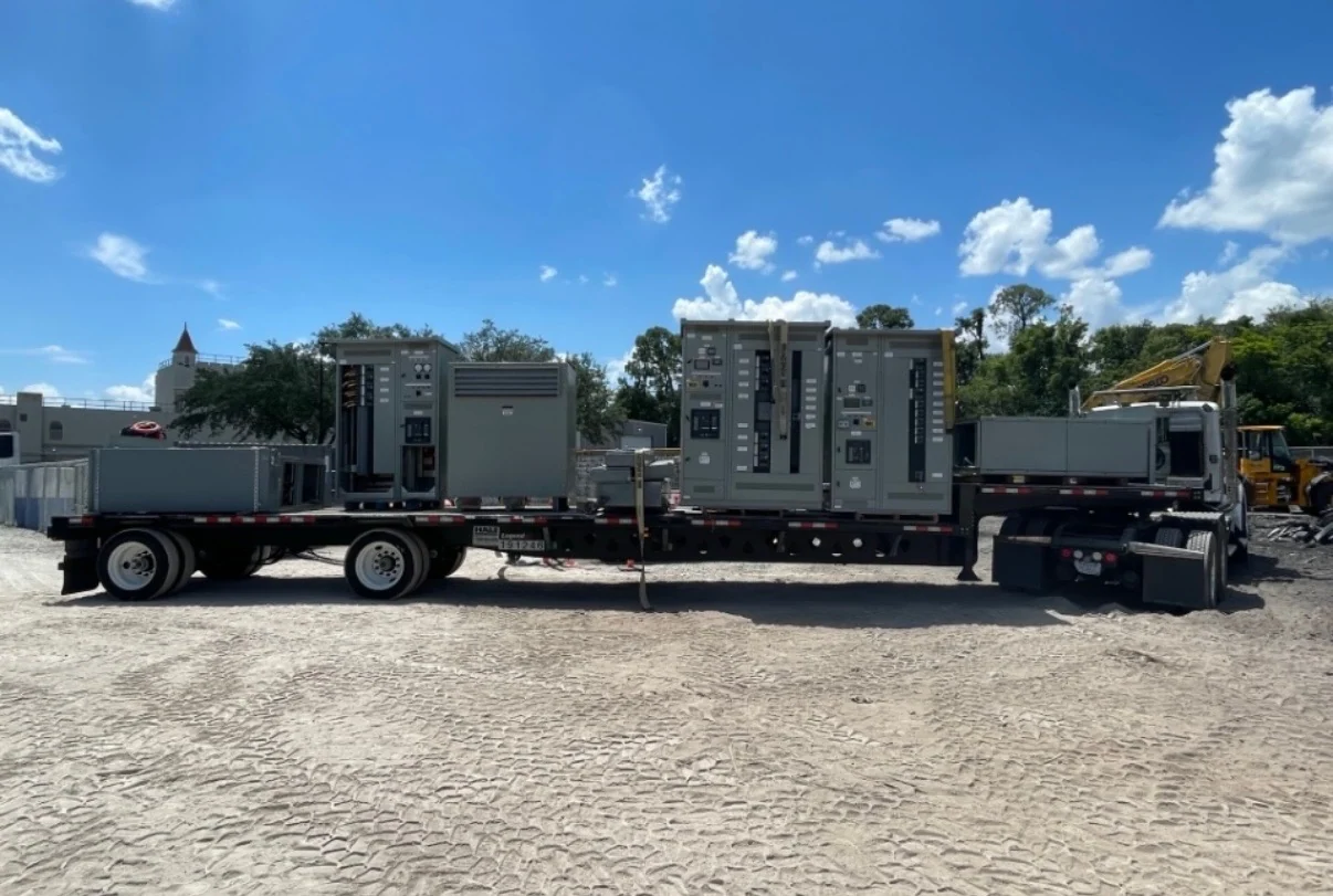
Useful busbar integration documentation identifies conductor material and size, phase and neutral markings, joint locations, support details, insulation provisions, clearances, hardware, torque instructions, and field-connection boundaries. During manufacturing, dimensional and workmanship inspections can compare the physical assembly with approved drawings, while project-defined electrical or functional checks can address continuity and related acceptance criteria. Shipping plans should preserve alignment, protect exposed interfaces, identify shipping sections, and communicate lifting and receiving requirements. As a direct manufacturer, Switchgear Builders can coordinate a custom new-equipment package, nationwide U.S. shipping, and the project records needed for installation review; timing is confirmed for the defined scope.