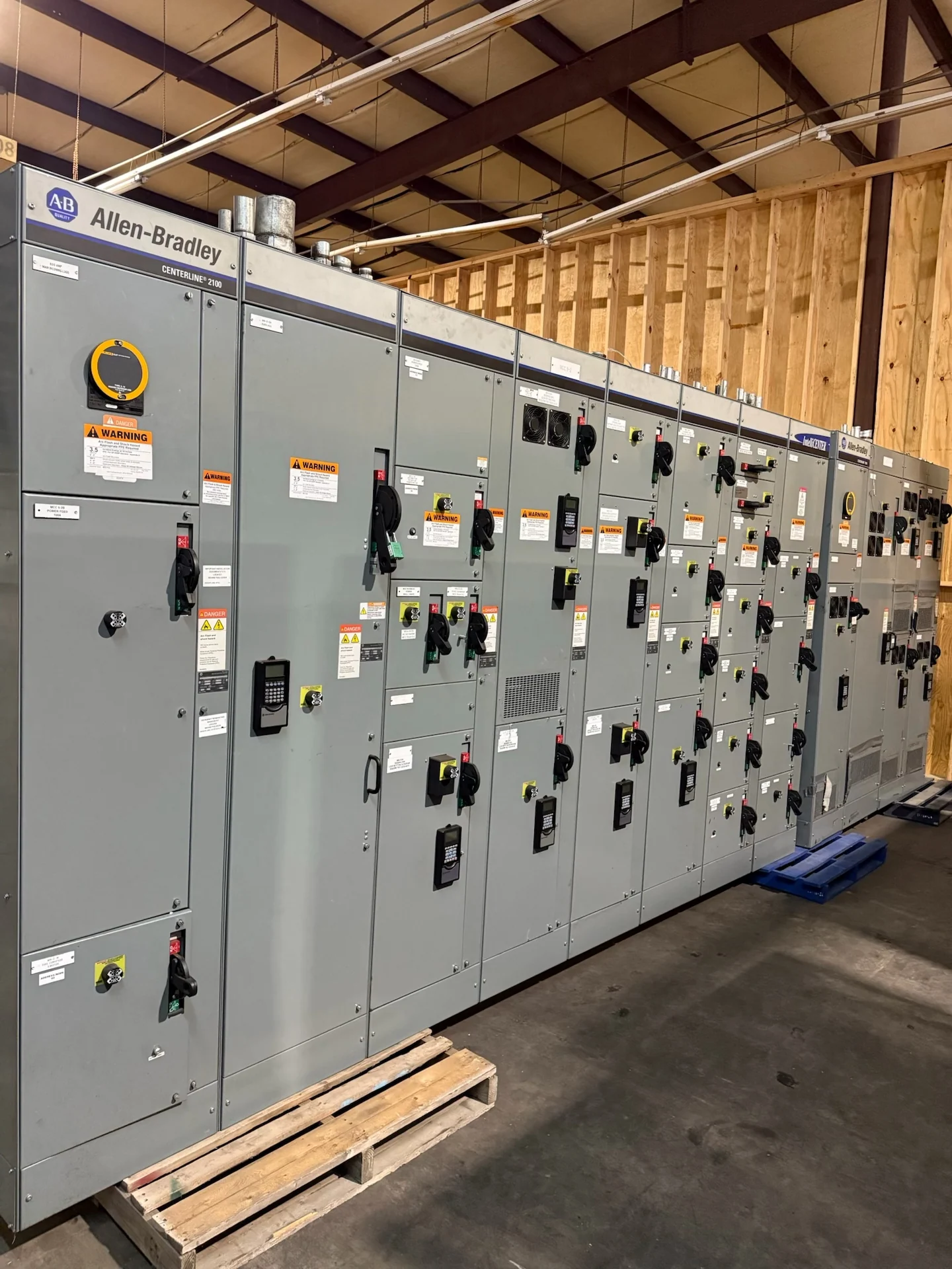
Start with a Clear Replacement Scope
An emergency switchgear replacement begins with a disciplined description of what must be restored, protected, and connected. Give the manufacturer the facility location, equipment function, affected source or feeder, nominal voltage, phase and wire arrangement, continuous current, available fault current, and any known short-circuit or interrupting requirements. Identify whether the assembly serves a service entrance, generator, transformer, motor load, or general distribution bus. A concise project description helps separate confirmed facts from assumptions before a custom new lineup is engineered, built, and supplied for the project.
Document the Existing Installation
Photographs and records are especially valuable when an outage creates pressure to act quickly. Send readable nameplate photographs, the latest one-line diagram, wiring or control diagrams, floor plans, lineup elevations, cable schedules, breaker information, and any prior test records that remain available. Measure overall dimensions, section widths, depth, height, cable-entry positions, conduit locations, bus connections, door swings, and working-space constraints rather than relying on memory. Note visible damage separately from information that still needs field verification by qualified personnel. Record the direction of cable approach, termination space, neutral and ground locations, and whether adjacent equipment must remain energized during installation. A marked-up photograph showing section boundaries and connection points can resolve ambiguities that a general room photograph cannot.
Define Safety and Operating Constraints
Emergency work does not remove the need for safe planning. The project team should identify isolation boundaries, required outages, temporary power arrangements, arc-flash study inputs, grounding and bonding interfaces, access restrictions, lifting paths, and the responsibilities of the electrical contractor and qualified commissioning personnel. Explain whether the replacement must preserve a main-tie-main sequence, source interlocks, shunt or undervoltage functions, metering, alarms, or remote signals. These details affect enclosure layout, control wiring, device selection, testing, and installation coordination.
Coordinate a Custom Manufacturer Quote
A useful request for pricing should distinguish mandatory requirements from preferred options. Include the desired lineup arrangement, protective-device types, bus material, enclosure environment, cable termination approach, control voltage, communications expectations, documentation list, witness requirements, destination, and freight or receiving constraints. Switchgear Builders manufactures new electrical switchgear in the United States, builds custom to specification, uses American components, and supports nationwide shipping coordination. Project-specific scope, feasibility, and commercial terms still require review with the manufacturer.
Confirm Fit Before Fabrication
Before fabrication, the responsible engineer and installer should reconcile the proposed replacement with the one-line diagram, protection study, utility or owner requirements, room clearances, anchorage, feeder routing, and field installation sequence. Compare every interface: incoming conductors, outgoing feeders, control circuits, communications, grounding conductors, neutral treatment, and access for maintenance. A replacement that matches a nameplate current but not the physical or electrical interfaces can create avoidable field changes, so drawing review and documented approvals are important even under urgent conditions. The review should also identify demolition limits, temporary supports, cable bend-radius concerns, phasing constraints, and the point at which settings or control logic will be transferred from the prior arrangement. Written responses to open items give the contractor a dependable basis for field execution.
Plan Delivery, Installation, and Verification
Nationwide shipping should be planned around the destination, shipping splits, section weights, lifting points, protective packaging, receiving access, and the qualified rigging resources identified by the project team. Agree on the documents and checks needed at receipt, then establish an installation and verification sequence covering torque, conductor terminations, grounding, control wiring, protective settings, interlocks, insulation or continuity checks where applicable, and functional tests defined by the project. The manufacturer can review the requested scope and confirm what response and delivery information is feasible for that specific emergency inquiry.