Start with the electrical and physical envelope
A useful switchgear enclosure layout begins with the equipment's electrical function and the room that will receive it. The one-line diagram, nominal voltage, continuous current, fault-duty information, device arrangement, cable direction, grounding approach, and control requirements establish the internal and external envelope. Room dimensions, working clearances, wall setbacks, floor elevation, door swing, and the route from unloading point to final position matter just as much. Switchgear Builders manufactures new electrical distribution equipment in the United States, custom to project specifications, so a quote should identify these constraints instead of relying on a generic cabinet footprint.
Arrange doors and removable panels for real access
Doors and removable panels should support the work technicians must perform, not merely make the enclosure look complete. Mark the locations of operating handles, meters, indication, terminals, adjustment interfaces, and inspection points, then distinguish areas needing routine access from areas opened only during installation or service. Door clearances should account for adjacent equipment and egress, while removable panels need practical fastener access and a safe handling method. A layout review should also identify whether a panel can be removed without disturbing wiring, barriers, or connected conductors.
Coordinate ventilation with heat and environment
Ventilation is a design coordination issue involving heat sources, enclosure construction, ambient conditions, dust, moisture, and the installation environment. Devices that dissipate heat, cable compartments, bus spaces, and control power components may require different treatment, but an opening or fan cannot be specified responsibly without considering ingress protection and maintenance access. For outdoor or demanding indoor locations, the project team should define exposure, enclosure expectations, corrosion concerns, and any filtration or separation needs. The manufacturer can then translate those requirements into a custom enclosure layout for review rather than assuming a standard vent pattern.
Separate power, control, and service paths
A clear enclosure layout helps keep power conductors, control wiring, communications, and service activities organized. The design should show cable entry zones, bend space, termination direction, terminal blocks, wireway, barriers, grounding points, and paths between compartments where applicable. Segregation decisions depend on the equipment arrangement and project requirements; they should be documented on drawings so installers know where conductors enter and technicians know which covers or panels provide access. Early coordination also reduces conflicts between a large feeder termination, a hinge line, a removable panel, and nearby control hardware.
Design for installation, lifting, and maintenance
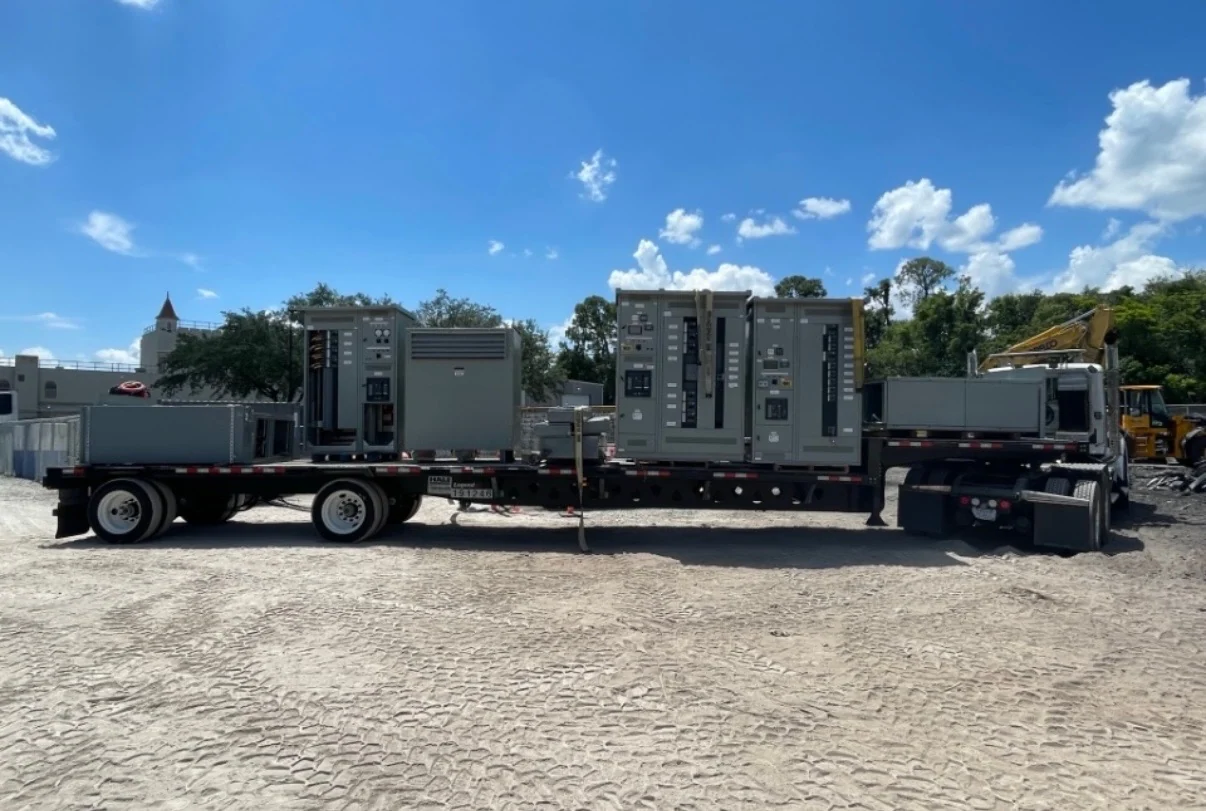
Service access extends beyond the front face of an enclosure. Review lifting points, shipping sections, base channels, anchoring surfaces, split lines, joining hardware, cable pulling space, and the sequence for placing each section in the electrical room. Consider the tools and hand clearance needed to remove a cover, replace a device, tighten a termination, or inspect a connection. The layout should identify responsibilities for field joining, alignment, grounding, and final installation, while a qualified electrical team confirms working space and site requirements before fabrication.
Turn the layout into a reviewable custom package
Before fabrication, a practical submittal package should make the enclosure decisions visible. Include an overall elevation, plan and side views, section details where depth matters, door and panel schedules, device locations, cable entry information, mounting details, ventilation features, and relevant weights or lifting data when available from the design. Mark assumptions and unresolved interfaces instead of hiding them. Switchgear Builders supplies new custom-built equipment with American components and nationwide shipping; project-specific manufacturing location, component details, documentation, and shipping arrangements should be confirmed during the quotation and drawing process. During review, compare the drawing against the installation sequence: receiving, moving, setting, joining, terminating, commissioning, and future service. Confirm that each planned action has enough physical space and that removable parts have an identified destination while work is underway. Record field dimensions that could affect the enclosure, such as wall penetrations, housekeeping pads, overhead obstructions, and cable-tray elevation. These details make the drawing more useful to engineers, contractors, and facility teams and help keep the final build aligned with the approved design.