Start With the Renewable-Energy System Boundary
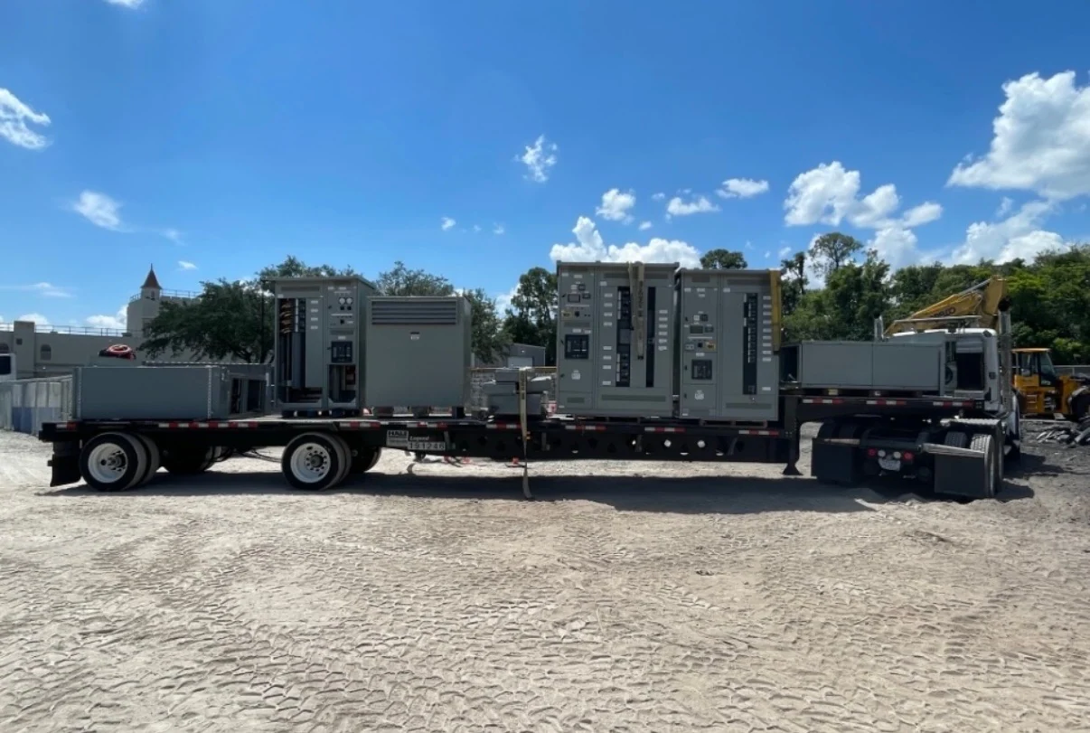
A renewable-energy switchgear package begins with a clear electrical boundary, not with a preferred enclosure or device list. Define whether the equipment sits at a solar array, wind collection point, battery interface, collector substation, facility service, or utility interconnection. Then document nominal voltage, frequency, phase arrangement, grounding method, continuous current, available fault current, and the operating sequence for normal, abnormal, and maintenance conditions. A one-line diagram, load or generation schedule, site elevation, environmental exposure, cable entry direction, and equipment-room or pad dimensions give the manufacturer useful design inputs. Each new switchgear build from Switchgear Builders is manufactured in the United States to specification, with American components and nationwide shipping; final configuration remains project-specific.
Interconnection Requirements Shape the Design
Generation interconnection equipment must coordinate the source, the utility interface, and the facility or collection network. A design team should identify the point of common coupling, utility metering provisions, isolation requirements, synchronizing or transfer logic where applicable, and the protection functions expected by the interconnecting authority. The specification should distinguish interrupting duty for individual protective devices from the short-circuit withstand or short-circuit current rating applicable to the complete assembly. Protection studies may establish pickup values, time delays, directional elements, or reclosing constraints, but those settings should be supplied by the responsible engineer rather than guessed during fabrication.
Collection Systems Need Coordinated Protection
Solar and wind collection systems can combine multiple feeders, step-up transformers, collector cables, sectionalizing points, and a larger interconnection transformer. Switchgear selection should account for feeder count, source contribution, transformer impedance, cable length, grounding equipment, and the consequences of isolating one section while other generation remains energized. For medium-voltage applications, verify voltage class, insulation coordination, basic impulse insulation level where applicable, switching duty, cable terminations, and control-power sources. For low-voltage sections, review bus capacity, breaker frame and trip characteristics, metering, and heat management. These details help a custom builder separate functional requirements from assumptions carried over from another project.
Enclosure and Site Interfaces Matter
Renewable installations often place electrical equipment outdoors or in locations exposed to dust, moisture, temperature swings, ultraviolet radiation, salt, or restricted maintenance access. Specify the applicable enclosure type or ingress protection requirement, drainage and ventilation expectations, door orientation, pad or foundation interfaces, cable trench geometry, lifting points, and working clearances. An outdoor arrangement may need a different layout from an indoor lineup even when the electrical ratings are similar. Site drawings should show transportation access, equipment splits, unloading space, and the route to the final position. The manufacturer can use those constraints to develop equipment dimensions and shipping sections coordinated with the installation plan.
Controls, Metering, and Documentation
A useful renewable-energy switchgear specification describes what operators must see and control as well as what the power circuit must interrupt. List local indications, remote contacts, metering quantities, communications protocol, control voltage, interlocks, permissives, trip circuits, breaker status points, and any interface with plant controls or a supervisory system. Identify required drawings, wiring diagrams, terminal schedules, nameplate data, component data, spare-device provisions, and test records before quotation. If UL 891 may apply to a low-voltage switchboard arrangement, confirm its applicability and any project-specific listing or verification requirements during engineering review; the standard should not be presumed to cover every switchgear configuration.
A Practical Manufacturer Quote Package
For a focused quote request, send the latest one-line diagram, equipment schedule, fault-study inputs, site and environmental information, physical layout, control narrative, utility requirements, and a list of owner-furnished interfaces. State whether the request concerns a collector feeder lineup, interconnection switchgear, transformer secondary equipment, or another defined boundary. Include the preferred shipping destination, packaging or lifting constraints, drawing-review expectations, required commercial inclusions, and desired project milestones. Direct manufacturer coordination can then address feasible ratings, American component preferences, custom fabrication details, documentation scope, and nationwide shipment planning. A disciplined information package reduces clarification cycles while leaving final engineering decisions to qualified project participants.