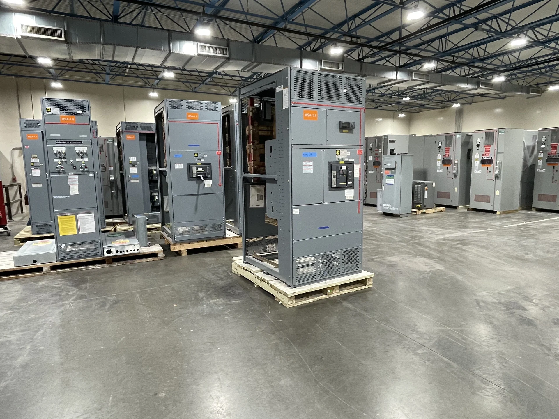
Start With the Interconnection Architecture
Solar interconnection switchgear sits between generation equipment and the electrical system that receives its output, so the design begins with a clear one-line diagram rather than a product label. Identify the utility or facility source, inverter outputs, transformers, collection conductors, service point, disconnecting means, and any alternate sources. The arrangement may call for a dedicated feeder, a common bus, a main device, a tie, or a transfer sequence. A manufacturer can build new custom switchgear to the approved electrical concept, but the final arrangement must follow the engineer’s study, utility requirements, and project-specific operating procedure.
Define Voltage, Current, and Fault Duties
A useful solar interconnection specification states nominal voltage, frequency, phase and wire configuration, grounding method, continuous current, available fault current, and the required interrupting or withstand duty for each relevant device and bus. Inverter output can differ from utility service characteristics, while transformer impedance and collector topology affect fault calculations. Do not size the lineup from array nameplate power alone. Confirm maximum export, import conditions where applicable, ambient conditions, conductor terminations, and future circuits with the responsible electrical designer before requesting a firm equipment configuration.
Coordinate Metering and Protection Interfaces
Metering and protective interfaces deserve their own review because the interconnection may involve revenue measurement, generation measurement, facility load measurement, or utility-required telemetry. The equipment package may need defined instrument-transformer locations, metering compartments, test provisions, relay inputs, breaker trip circuits, and communication interfaces, depending on the approved scheme. Provide the utility’s metering diagram, protection philosophy, relay requirements, and point-of-connection rules when available. This prevents a physically workable lineup from missing an essential interface that must be coordinated with controls, commissioning, or utility review. Identify which party provides each metering signal and which party verifies it during commissioning.
Account for Grounding and Operating Sequences
Solar facilities can combine grounded and separately derived systems, inverter controls, transformers, and utility-connected equipment, making grounding and switching logic central to the equipment design. Document where the system neutral is established, how equipment grounding and bonding are arranged, and how islanding prevention or interconnection protection is addressed by the project design. Define normal, abnormal, maintenance, and re-energization sequences, including which devices may close together and which must be interlocked. Switchgear builders can translate approved sequences into controls and wiring, subject to engineering review and field acceptance responsibilities.
Plan the Enclosure, Access, and Installation Interfaces
Physical conditions often determine whether an interconnection lineup is practical. Identify indoor or outdoor placement, environmental exposure, cable entry direction, working clearances, equipment-room access, foundation or housekeeping-pad dimensions, lifting limits, shipping splits, and the location of adjacent transformers or inverter skids. Include conductor bend space, termination hardware, removable panels, ventilation needs, and service access in the layout review. These details help a manufacturer develop new switchgear with American components to the project specification and plan nationwide shipment for the installation site.
Prepare a Complete Manufacturer Quote Package
For a meaningful quote, send the current one-line diagram, load and generation data, fault study or preliminary fault values, utility interconnection requirements, metering documents, protection and control narrative, equipment location, dimensions, cable schedules, preferred device arrangement, drawings required for approval, testing expectations, destination, and requested commercial terms. State whether UL 891 is applicable to the proposed assembly and ask for project-specific confirmation of applicability and any listing requirements; UL 891 should never be assumed for every switchgear type. Switchgear Builders manufactures, builds, and supplies new electrical switchgear in the United States, using American components and shipping nationwide, with final scope established for each project.