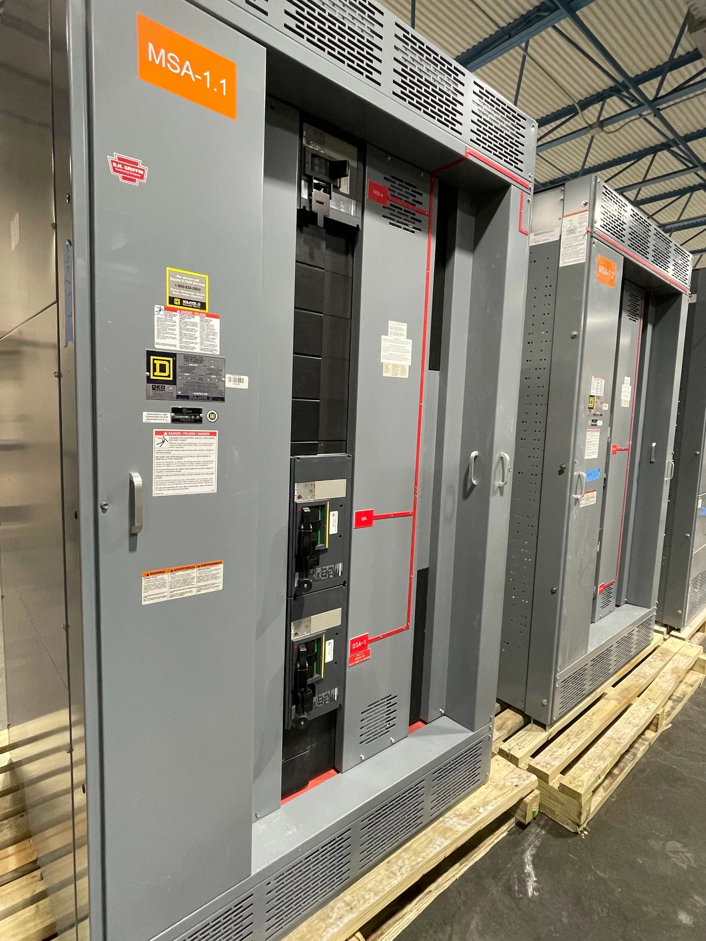
Planning Little Rock Outdoor Distribution
A Little Rock electrical distribution project begins with the circuit function, source arrangement, and physical setting rather than a catalog label. Pad-mounted switchgear can organize switching and protection for outdoor feeders, transformer interfaces, or sectionalized distribution circuits, but the correct configuration depends on the one-line diagram and operating sequence. A useful design review identifies nominal system voltage, phase and grounding arrangement, continuous current, available fault current, switching duty, feeder count, and whether operators need visible isolation, load interruption, or fault protection. Switchgear Builders manufactures new electrical switchgear in the United States, builds custom to specification with American components, and supplies equipment for nationwide shipping; project drawings and engineering requirements determine the final assembly.
Switching Duty and Protection Inputs
Switching duty should be stated in functional terms so the equipment matches the circuit and the people who will operate it. The specification may need to distinguish normal-load switching from fault interruption, sectionalizing, transformer protection, or a planned tie between feeders. Identify the protective devices, ratings, fuse or breaker approach where applicable, interlocks, operating handles, indicators, and control power requirements before requesting a custom switchgear quote. A coordination study can establish how the outdoor assembly relates to upstream and downstream devices, while the available-fault-current calculation helps the design team evaluate short-circuit requirements. Do not infer a rating from the city or state; the project electrical data controls selection.
Enclosure Exposure in Arkansas
Outdoor enclosure selection for a Little Rock site should account for rain, humidity, sunlight, temperature variation, wind-driven moisture, dust, corrosion sources, and the way water can collect around the pad. Specify the intended enclosure type and environmental requirements with the engineer, including door construction, sealing, drainage, finish, ventilation, barriers, and access control. The surrounding site may introduce irrigation spray, standing water, lawn chemicals, roadway debris, or nearby industrial contaminants, so a generic outdoor label is not enough. Confirm whether the assembly requires internal heaters, thermostatic controls, space for cable terminations, or separation between compartments; each choice affects heat, maintenance, dimensions, and documentation.
Cable Entry and Pad Interfaces
Cable entry is a coordination item between the switchgear builder, civil designer, electrical contractor, and utility or owner standards. Establish cable quantity, conductor size, bending radius, termination type, phase arrangement, entry direction, grounding conductor path, and the locations of incoming and outgoing circuits. The concrete pad, conduit bank, grounding electrode system, and equipment anchorage must align with the enclosure footprint and termination space. For a custom pad-mounted switchgear arrangement, provide a dimensioned site plan and section when available, including finished grade, access side, barriers, bollards, drainage, and nearby structures. These details reduce field conflicts without assuming that a particular utility or installation method applies.
Access, Operations, and Maintenance
Site access should be reviewed before fabrication because a compact enclosure still needs safe approach space, door swing clearance, working room, and a practical route for delivery and placement. Consider whether a crane, forklift, or other qualified rigging method can reach the pad; document overhead obstructions, gates, slopes, turning radii, temporary closures, and final maintenance access. The owner should define normal and abnormal switching procedures, labeling, lockout provisions, key interlocks, and who is authorized to operate the equipment. A project package can then align the lineup layout, nameplates, wiring diagrams, and operating information with the actual field arrangement.
Building a Project-Specific Package
A complete inquiry for Little Rock electrical distribution equipment should include the one-line diagram, load and fault calculations, site and pad drawings, environmental conditions, cable schedule, utility or owner requirements, preferred devices, control logic, and documentation expectations. Ask the manufacturer to identify assumptions, exclusions, required approvals, and information still needed before fabrication. If the project specification references UL 891, confirm its applicability to the particular assembly and separately confirm any project-specific listing or verification requirements; that reference does not establish a blanket listing for every configuration. Switchgear Builders can use the submitted requirements to develop new custom equipment and coordinate nationwide shipping details, while the project team remains responsible for installation, field coordination, and applicable engineering review.