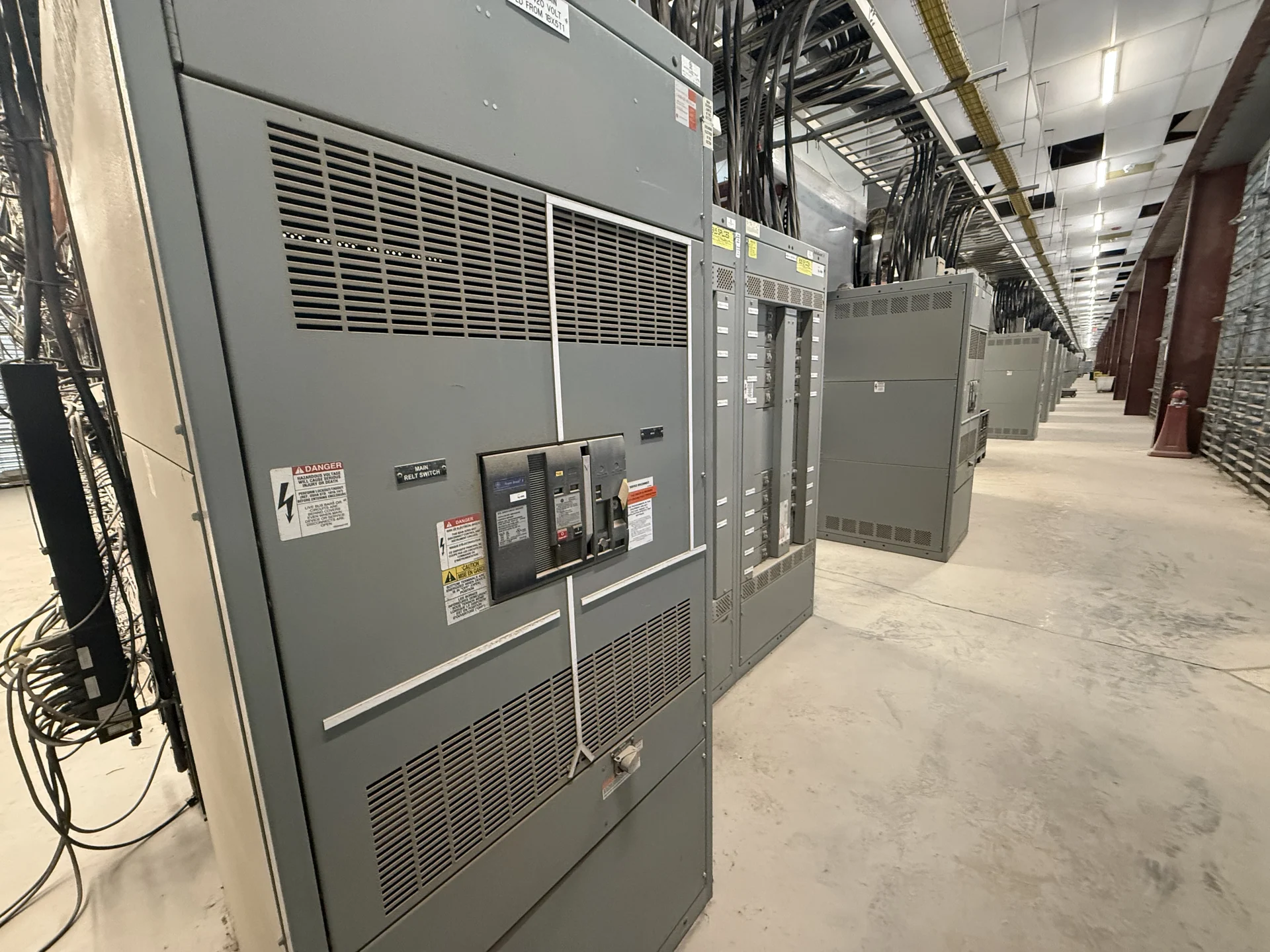
Start With the Delaware Facility’s Critical Loads
Planning Delaware switchgear for automatic transfer switches begins with identifying which facility loads require an alternate source and how those loads behave during a transfer. A healthcare space, water facility, data room, manufacturing process, or commercial building may divide essential and nonessential circuits differently. Document normal voltage, phase, frequency, connected load, starting current, and expected growth for each load group. Note loads that must remain energized, loads that can wait, and loads that should be blocked during source instability. That information lets the design team establish source capacity and determine whether the transfer equipment should serve one common emergency bus or several selectively coordinated branches.
Define Source Capacity and Transfer Sequence
An automatic transfer switch is only as useful as the sources and operating sequence around it. For a Delaware project, provide the utility service data, generator or alternate-source capacity, grounding arrangement, available fault current, and any required source separation. Then describe what should happen when the normal source falls outside its accepted limits: sensing, engine start or source readiness, transfer, retransfer, cooldown, and behavior after a momentary disturbance. Define acceptable sensing delays and retransfer conditions only after the facility team understands their effect on processes and occupants. The final sequence must be reviewed against actual equipment, load priorities, and the facility’s operating procedures rather than assumed from a generic diagram.
Coordinate Protection Across the Distribution System
Protection coordination deserves early attention because transfer equipment connects sources with different fault characteristics and response times. Review main and feeder protective devices, interrupting duties, time-current behavior, generator decrement characteristics where applicable, and the settings needed for selective operation. Include neutral and ground-fault treatment where the system design requires it, especially when source switching changes the grounding relationship. The switchgear arrangement should show where overcurrent protection, bypass or isolation functions, metering, and control wiring fit physically. A qualified electrical engineer can use the one-line diagram and study inputs to confirm that source switching does not create an avoidable trip or leave a critical load without the intended protection.
Plan Maintenance Access and Safe Operation
Maintenance access should influence the lineup before dimensions are finalized. Confirm room clearances, door and panel swing, cable entry, lifting and handling paths, ventilation needs, working space, and access to the automatic transfer switch controls and terminals. Ask how operators will test the transfer sequence, isolate equipment for service, and return the system to normal without confusing source status. Consider where test instruments, replacement components, and operating instructions will be used, while keeping controls identifiable to authorized personnel. These practical details can affect enclosure arrangement, shipping sections, control-circuit labeling, and the placement of disconnecting or bypass features that the project actually requires.
Specify a Custom New Equipment Package
Switchgear Builders manufactures new electrical switchgear in the United States, custom to specification, using American components and offering nationwide shipping. A useful inquiry should include the Delaware destination, one-line diagram, source information, load schedule, transfer sequence, dimensions, environmental conditions, utility requirements, control and metering points, documentation expectations, and installation interfaces. The manufacturer can use those inputs to develop a project-specific scope for review. Do not treat a catalog phrase or preliminary concept as confirmation of ratings, configuration, availability, or delivery details for the finished equipment.
Coordinate Delivery With the Delaware Site
Nationwide shipping does not eliminate the need for site logistics. Before release, coordinate the delivery address, receiving hours, truck access, unloading responsibility, rigging path, floor or foundation interfaces, equipment split dimensions, lifting points, and protection from weather during handling. Compare the approved drawings with the route into the electrical room and identify who will verify equipment condition, complete field connections, and perform commissioning checks. Include project-specific service and delivery questions in the quote request so commercial assumptions are visible before fabrication and shipment are planned.