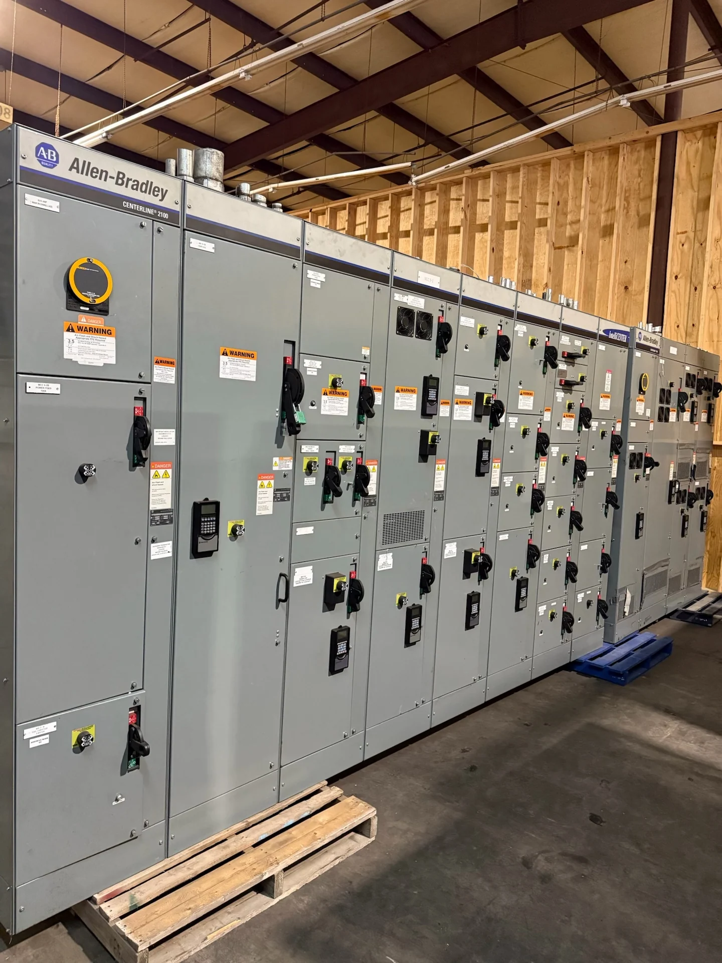
Start with the Critical-Load Definition
Planning automatic transfer switches for critical loads in Wilmington, Delaware begins with identifying what must remain energized, what can tolerate a brief interruption, and what should be disconnected during an abnormal source condition. A hospital area, pumping system, communications room, commercial building, or industrial process may each require a different transfer strategy. List every intended load, its voltage and phase, starting characteristics, operating sequence, and consequences of losing power. A qualified electrical engineer should confirm the essential-load classification, feeder arrangement, and applicable local project requirements before a manufacturer develops equipment information. For a Wilmington facility, map critical loads by feeder rather than grouping them only by room name. Note whether medical equipment, controls, pumps, refrigeration, or communications systems have inrush, harmonic, or sequencing behavior that could influence transfer performance. Mark loads that must remain isolated from a generator until voltage and frequency stabilize, and identify any load that requires a dedicated neutral or grounding arrangement.
Confirm Source Capacity and Transfer Sequence
An automatic transfer switch cannot be selected responsibly from load names alone. The design team should document normal and alternate source capacity, available fault current, voltage, frequency, grounding method, phase configuration, and the generator or alternate-source operating limits. Define whether transfer is open transition or another project-required sequence, what sensing conditions initiate transfer, and how retransfer occurs after the normal source returns. Time delays, engine start contacts, emergency stop provisions, and load-shed logic may affect the switchgear lineup, so the one-line diagram and control narrative need to agree before a quote is requested. Document which loads can restart together after transfer and which require staged restoration. Also identify the alternate source's short-time capability and response to motor starting, transformer energization, and simultaneous load pickup. State source-failure sensing, generator start, permissive checks, transfer, retransfer, cooldown, and failed-start alarm behavior in the written sequence. This gives the manufacturer a concrete control reference instead of leaving timing assumptions in meeting notes.
Coordinate Protection and Distribution Interfaces
Protection coordination is central to critical-load transfer planning. Review upstream overcurrent devices, downstream feeder protection, generator breaker settings, selective coordination objectives where required, and the interrupting or withstand duties of connected equipment. An automatic transfer switch may sit within a larger switchboard or switchgear arrangement, making bus ratings, conductor routing, bypass provisions, metering, and isolation points important to the overall design. The engineer should provide time-current information and fault-study inputs rather than relying on a generic device description. Final settings and interfaces remain specific to the electrical system and installation.
Design for Maintenance and Safe Access
Critical-load equipment should be planned around maintainability as carefully as initial operation. Identify working clearances, door swing, cable entry, lifting and movement paths, ventilation, heat dissipation, environmental exposure, and access for inspection or component replacement. Ask how the operating team will test source sensing, exercise the alternate source, isolate equipment, and restore service without creating an unintended outage. A project may require bypass or isolation features, remote indications, alarm contacts, or communications interfaces; each should be stated in the control schedule and checked against the installation space.
Prepare a Useful Manufacturer Inquiry
For a project in Wilmington, provide the manufacturer with the single-line diagram, load schedule, source data, transfer narrative, enclosure location, dimensions, cable-entry direction, control voltage, metering needs, and requested drawings or test records. Include the facility type, installation environment, delivery destination, responsible engineer, and any utility or authority review points. Switchgear Builders manufactures new electrical switchgear in the United States, builds custom to specification, uses American components, and ships nationwide. The final equipment scope should follow the project documents, transfer requirements, and engineering review.
Review the Submittal Before Release
Before releasing an automatic transfer switch or associated switchgear package for fabrication, compare the approved submittal with the one-line diagram, schedules, sequence of operations, physical room drawings, and installation responsibilities. Check source and load terminals, phase identification, grounding and bonding, protective-device coordination, alarm points, labels, spare provisions, and shipping sections. Confirm whether any requested standard, listing, or inspection requirement applies to this particular assembly; UL 891, for example, must be evaluated for project applicability rather than assumed. Record open items so the electrical contractor, engineer, owner, and manufacturer share the same basis of design.