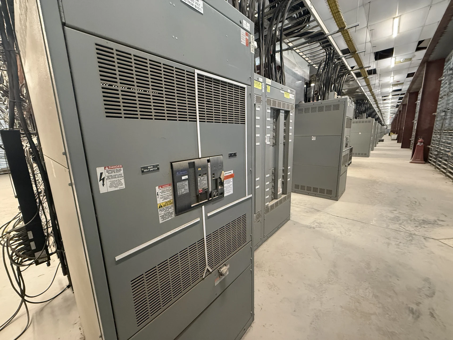
Start With the Georgia Project Record
Planning Georgia switchgear begins with a clear picture of the facility, the proposed expansion, and the electrical distribution changes required. Gather the latest one-line diagram, utility information, service voltage, phase and frequency, available fault current, calculated load, feeder schedule, grounding arrangement, and the intended location of each lineup. Include panel schedules and field dimensions where the new equipment must connect to an existing system. This information lets a manufacturer distinguish a new feeder addition from a broader service or distribution redesign before a quote is prepared.
Coordinate New Feeders With Existing Equipment
A facility expansion rarely stands alone electrically. New Georgia electrical distribution may need to connect to an existing service, bus section, transformer secondary, generator source, transfer equipment, or building feeder. Confirm termination space, conductor size, cable-entry direction, phase arrangement, bus position, equipment depth, working clearances, and the physical path into the electrical room. Existing drawings should be compared with field conditions by qualified personnel, because undocumented modifications can change the required interface. A custom manufacturer-built lineup should reflect those verified connection points rather than relying on a generic footprint.
Evaluate Load Growth and Protection
Expansion planning should account for both the immediate connected load and a defensible allowance for future circuits. Identify motor loads, heating or cooling equipment, process loads, receptacle demand, standby sources, and any nonlinear or sensitive loads that affect the design review. Specify continuous-current requirements, main and feeder protective devices, interrupting or withstand duties as applicable, and the coordination study inputs available to the engineer. A larger ampere rating alone does not resolve fault duty, selectivity, arc-flash objectives, or physical space. Those decisions belong in the project engineering process and must match the actual Georgia facility.
Plan Outage Windows and Installation Access
An expansion project should define how the new lineup will arrive, be positioned, connected, and commissioned without assuming that an outage plan is simple. Map the route from the receiving point to the electrical room, including doors, turns, floor loading, lifting restrictions, staging space, and any sections that must ship separately. Coordinate shutdown boundaries, temporary power, lockout procedures, testing responsibilities, and the sequence for energizing new feeders with the owner, engineer, electrical contractor, and qualified site personnel. The manufacturer can use these project inputs to shape enclosure sections, lifting provisions, documentation, and shipment coordination.
Build to the Project Specification
New electrical switchgear is manufactured by Switchgear Builders in the United States, with American components, project-specific construction, and nationwide shipping. For a Georgia inquiry, provide the equipment schedule, drawings, required devices, enclosure environment, metering needs, control voltage, interlocking sequence, labeling conventions, and submittal expectations. The resulting design should identify assumptions, exclusions, required approvals, and interfaces that remain the responsibility of the project team. If a specification references UL 891, confirm its applicability, construction requirements, and any project-specific listing needs for the exact assembly rather than treating the reference as a blanket product claim.
Coordinate Delivery and Closeout
Nationwide shipping makes destination planning part of the Georgia switchgear specification, not an afterthought. State the delivery address, site contact, receiving hours, dock or crane limitations, unloading responsibility, packaging expectations, and whether the equipment must be divided into shipping sections. Before release, align approved drawings, nameplates, terminal schedules, protection settings, test procedures, spare-part requirements, and installation documentation with the responsible engineer and contractor. Confirm project-specific service and delivery details directly with the manufacturer, since availability, freight arrangements, and field responsibilities depend on the final scope.