Start With the Industrial Feeder Architecture
Medium-voltage switchgear for industrial facilities in Atlanta, Georgia, should begin with the electrical architecture rather than a catalog label. Identify incoming utility or generation sources, feeder count, transformer locations, motor loads, process loads, and any normally open or normally closed ties. A site plan should show cable routes, room boundaries, outdoor exposure, access paths, and the points where new equipment connects to transformers and downstream distribution. This information lets a manufacturer develop new custom switchgear around the actual system, while the engineer confirms applicable Georgia requirements, utility criteria, and installation clearances. Switchgear Builders manufactures, builds, and supplies new electrical switchgear in the United States, using American components and shipping nationwide; the project package should still define every required component and interface before a quote is treated as complete.
Define Voltage Class and Insulation Requirements
The specified system voltage is only one part of a medium-voltage switchgear definition. The design team should identify nominal and maximum system voltage, frequency, phase arrangement, grounding method, basic insulation level where applicable, continuous current, and the environmental conditions at the Atlanta site. Transformer primary connections need particular attention: provide winding configuration, available tap information, grounding connection, inrush considerations, and the intended primary protective device. Cable termination type, conductor size, entry direction, bending space, and phase spacing can materially affect enclosure dimensions. These inputs help separate equipment voltage class from the facility's operating voltage and prevent a quote from quietly assuming a connection detail that belongs in the engineered design.
Coordinate Fault Duty and Bus Requirements
Available fault current should be established at each relevant bus and feeder point before selecting interrupters, fuses, bus conductors, supports, and grounding provisions. Request the utility contribution, transformer impedance and rating, generator contribution if present, motor contribution where applicable, and the clearing assumptions used in the study. The equipment specification should state the required short-circuit withstand or interrupting capability in the manner appropriate to the selected construction, with the engineer responsible for confirming the final values. Bus sectioning and tie arrangements also deserve a one-line review because alternate sources can change fault duty and operating sequences. A project-specific design can then address bracing, compartment boundaries, cable terminations, and protection coordination together instead of treating fault current as an isolated breaker number.
Plan Protective Relaying and Operating Logic
Protective relaying for an industrial feeder lineup should be described by function and operating sequence, not just by a device name. Define the faults and abnormal conditions to detect, CT ratios and locations, voltage inputs, trip paths, breaker or switch operation, lockout behavior, communications, event records, and any coordination with transformer secondary devices. If the facility has parallel sources, a bus tie, generators, or large motors, document which source combinations are permitted and how interlocks should prevent an unintended connection. Time-current coordination, arc-flash study inputs, grounding method, and relay settings remain engineering responsibilities. A manufacturer can build the requested new assembly around approved drawings and control logic, but the quote should clearly identify supplied devices, wiring, terminals, and documentation rather than implying a universal relay package.
Prepare a Complete Custom Equipment Inquiry
A useful inquiry for Atlanta-area industrial facility feeders should include the single-line diagram, load schedule, utility data, fault study, transformer schedule, site and room drawings, cable schedule, elevation or footprint limits, environmental conditions, and the desired operating sequence. Add questions about metering, space heaters or ventilation where relevant, access doors, lifting provisions, finish, labels, spare provisions, remote interfaces, and documentation. Ask the manufacturer to identify assumptions, exclusions, required approvals, inspection points, testing scope, and shipping sections. Switchgear Builders can use this information to prepare custom new equipment to the project specification, with American components and nationwide shipping from the manufacturer. Any requested standard, listing, or utility acceptance condition must be reviewed for this specific configuration before it is included as a project requirement.
Coordinate Delivery and Field Integration
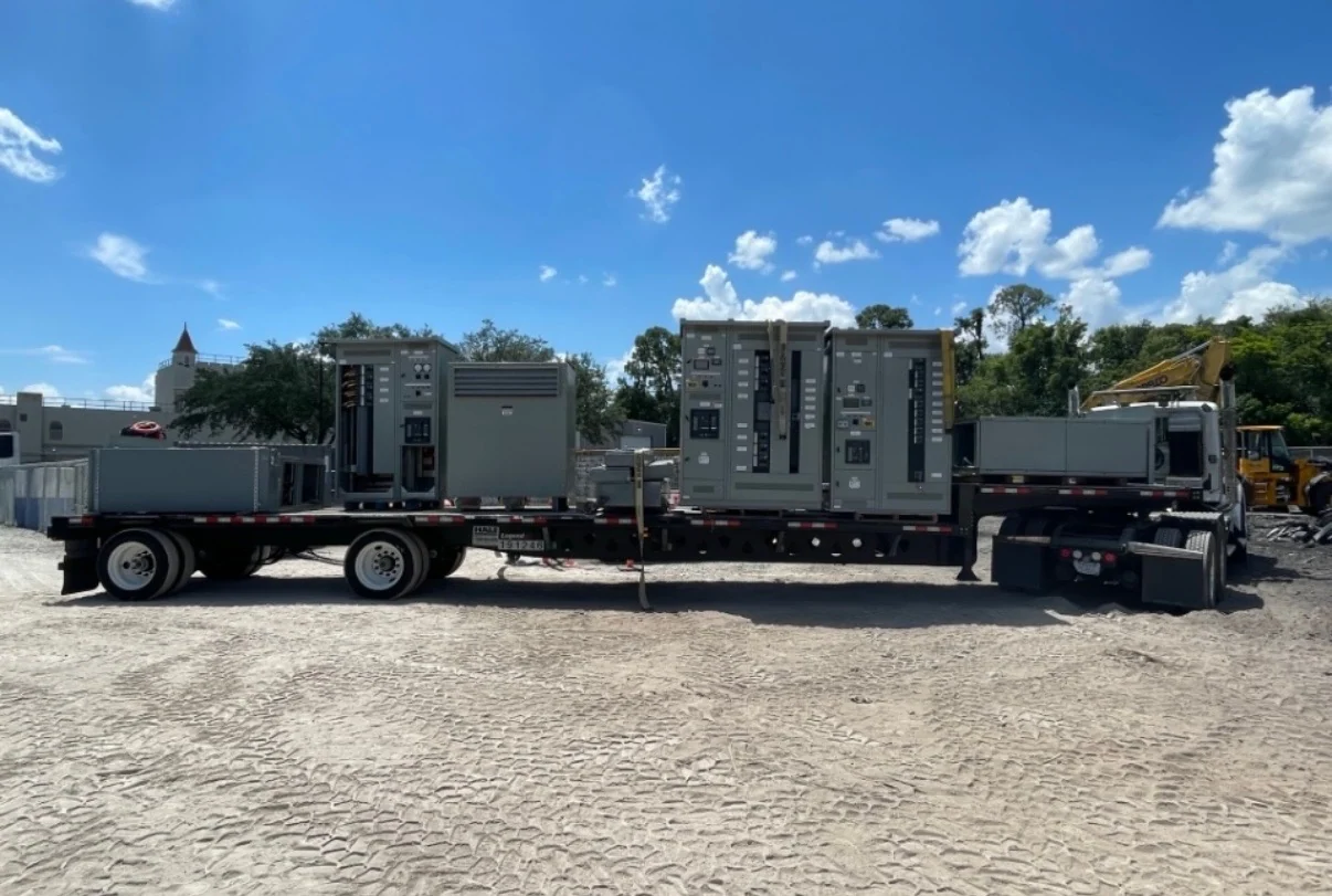
Delivery planning is part of the electrical design because medium-voltage lineups may arrive in shipping sections that must pass through the facility's actual route. Confirm section dimensions, weights, lifting points, receiving hours, staging space, indoor storage, rigging responsibility, and the sequence for setting, joining, terminating, grounding, and inspecting the equipment. The electrical contractor and qualified site personnel should coordinate outage boundaries, cable preparation, torque requirements, testing, relay commissioning, and energization procedures under the project safety plan. Nationwide shipping can support an Atlanta, Georgia destination, but freight arrangements, packaging, transit estimates, and site readiness should be confirmed for the specific order. Final acceptance should rely on approved drawings, recorded project tests, and the engineer's commissioning process rather than an assumed blanket performance claim.