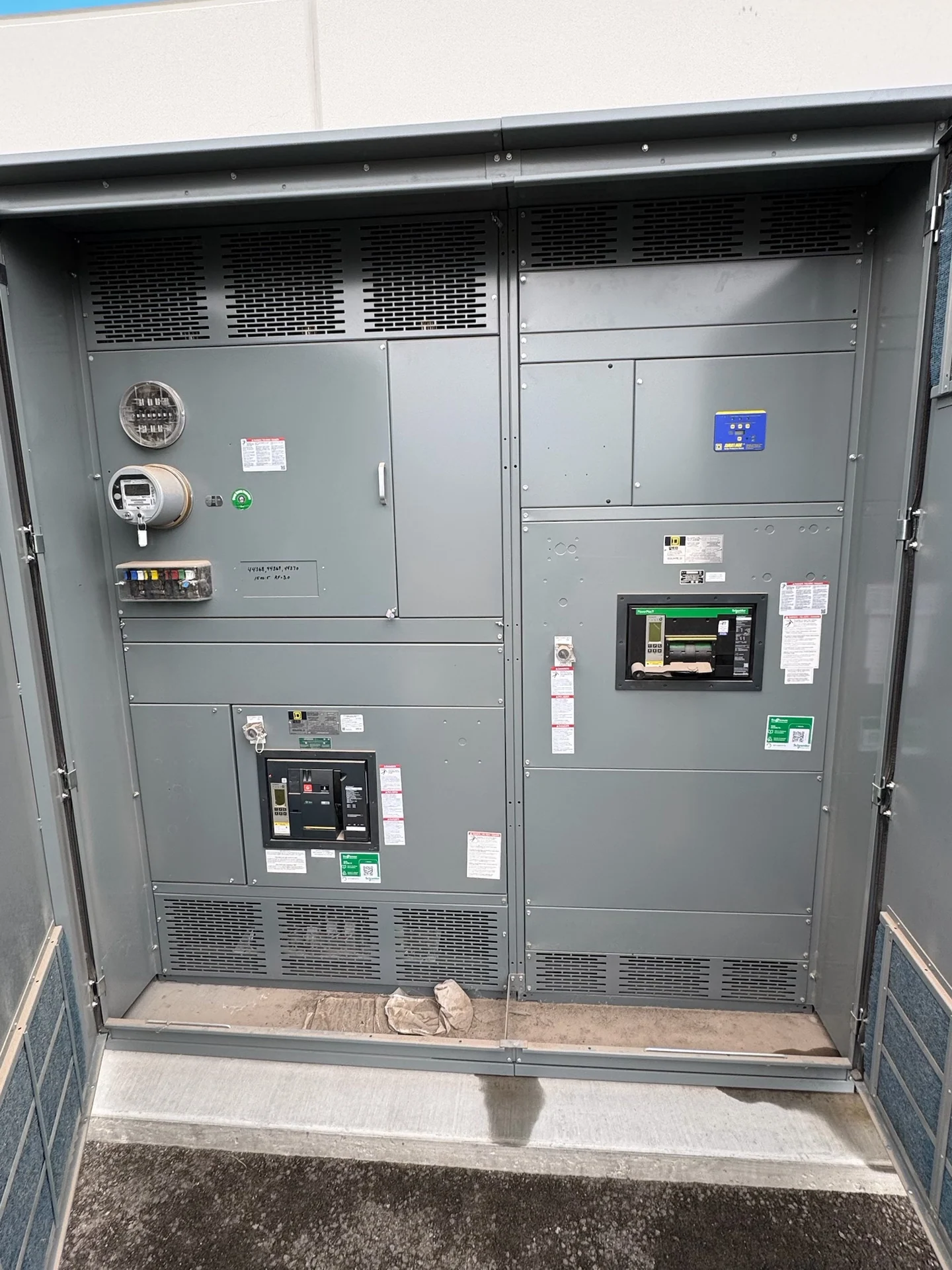
Plan the Kentucky Distribution Context
Kentucky switchgear projects can involve commercial sites, manufacturing facilities, utilities, campuses, and rural distribution points, so the equipment specification should begin with the system function rather than a preferred enclosure. For a pad-mounted switchgear application, identify the source, downstream feeders, nominal voltage, phase arrangement, grounding method, continuous load, available fault current, and intended switching sequence. Switchgear Builders manufactures new electrical switchgear in the United States, builds custom equipment to specification, uses American components, and supplies projects with nationwide shipping. The final design still depends on project engineering, utility requirements, site conditions, and the installation plan.
Define Switching Duty and Protection
Switching duty determines how the pad-mounted assembly is expected to operate during normal service, isolation, feeder sectionalizing, maintenance, or a fault response. A useful inquiry distinguishes load interruption from isolation, identifies whether fuses, switches, circuit breakers, or other protective devices are contemplated, and documents the operating sequence for each source and feeder. Engineers should compare available fault current with the specified withstand and interrupting requirements, then coordinate protective characteristics with upstream and downstream devices. Avoid selecting a device from a nominal voltage label alone; the complete electrical duty and coordination study govern the project-specific configuration.
Account for Outdoor Enclosure Exposure
Outdoor distribution in Kentucky requires a deliberate review of weather exposure, drainage, condensation, temperature variation, sunlight, dust, vegetation, corrosion risk, and the possibility of contact with water or deicing materials. The enclosure approach should match the installation environment and the access method, while doors, hinges, latches, barriers, operating handles, and grounding provisions should be reviewed as part of the complete assembly. Provide the site elevation, proposed orientation, surrounding grade, and any special environmental information with the request for quotation. Enclosure ratings and construction details must be confirmed against the project specification and applicable engineering requirements rather than assumed from the word pad-mounted.
Coordinate Cable Entry and Site Interfaces
Cable entry can control the practical layout of pad-mounted switchgear as much as the electrical one-line diagram. Identify cable quantity, conductor size and type, termination method, phase spacing, bend radius, neutral or grounding conductors, and whether the cables approach from below, beside, or through a defined duct-bank arrangement. Show transformer, utility, feeder, and communications interfaces where relevant, and reconcile them with the foundation, vault, trench, and pull-space drawings. A manufacturer can use these inputs to develop a custom enclosure and internal arrangement, but field dimensions, utility standards, and installation responsibilities should be resolved before fabrication is authorized.
Review Access, Handling, and Maintenance
A Kentucky project plan should account for how the equipment reaches its final position and how qualified personnel will approach it after installation. Confirm the delivery destination, road and gate limitations, turning radius, unloading area, lifting method, foundation readiness, working clearances, and any restrictions on truck or crane access. The operating side should remain accessible without conflicting with fences, landscaping, parked vehicles, or drainage features. Define who supplies rigging, who verifies the foundation, and who performs field connections. Switchgear Builders can coordinate a new custom equipment shipment nationwide, while site access, installation, and field acceptance remain project-specific responsibilities.
Prepare a Complete Manufacturer Inquiry
For a useful quote on pad-mounted switchgear for outdoor distribution circuits, send the one-line diagram, equipment schedule, site location, voltage and frequency, phase and grounding information, load and fault data, switching narrative, protection preferences, enclosure requirements, cable and termination details, foundation interfaces, drawings, documentation expectations, and desired shipping arrangement. Include the Kentucky authority or utility criteria that apply to the project, but do not assume a statewide configuration. The manufacturer can then identify open technical questions, develop a custom scope, and state project-specific service and delivery details. Any UL 891 applicability, listing, or other certification question must be confirmed for the exact assembly and project.