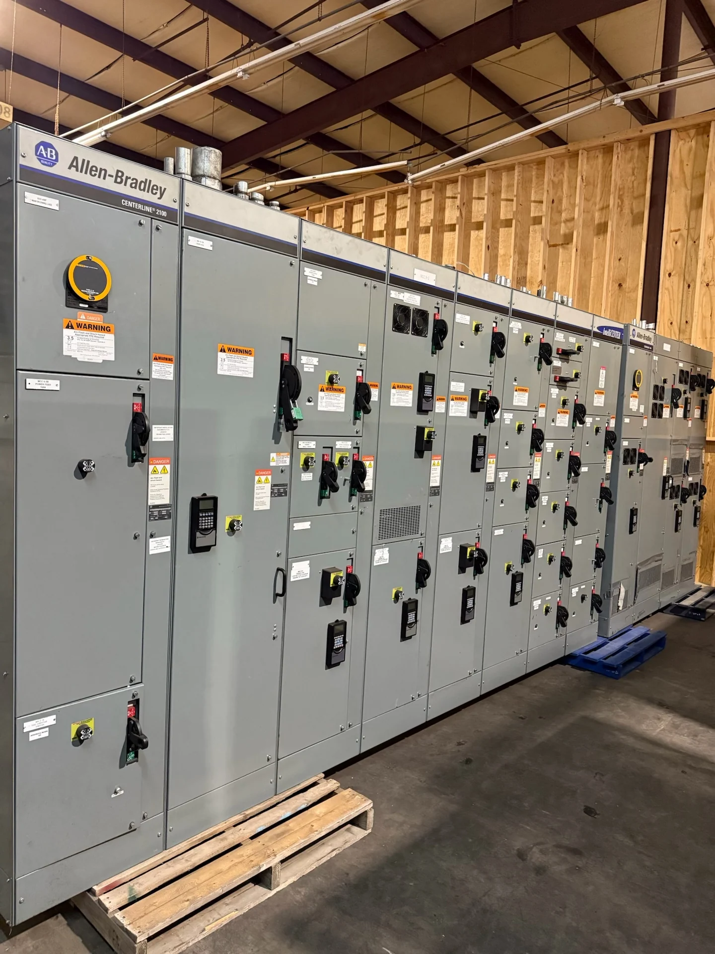
Start with the Lexington Distribution Scenario
Pad-mounted distribution switchgear can organize outdoor switching and protection where underground feeders, transformers, and service points meet. For a Lexington, Kentucky project, the useful starting point is not a city label but a defined one-line diagram, system voltage, grounding method, continuous current, available fault current, and operating sequence. For each specification, Switchgear Builders manufactures new electrical switchgear in the United States using American components and ships nationwide. A project inquiry should identify whether the assembly serves a loop, radial feeder, sectionalizing point, transformer connection, or another arrangement so the proposed equipment is matched to the actual distribution plan.
Define Switching Duty and Protection
Switching duty determines what the pad-mounted assembly must do during normal operation, feeder isolation, maintenance, and an abnormal condition. Specify whether each device will interrupt load current, provide visible isolation, coordinate with fuses, or interface with upstream and downstream protective equipment. Include fault-duty calculations, feeder conductor information, transformer data where applicable, relay or control requirements, and the intended operating sequence. A manufacturer can use those inputs to develop a new custom configuration, but final device selection and settings remain matters for the responsible electrical engineer and the project protection study.
Plan the Enclosure for Outdoor Exposure
Outdoor exposure in Lexington requires a deliberate review of precipitation, temperature variation, drainage, condensation risk, corrosion conditions, landscaping, traffic, and public access. The enclosure arrangement, finish, door hardware, barriers, ventilation approach, and access provisions should follow the project environment and applicable specifications rather than an assumed standard package. Ask for the intended enclosure requirements, grounding and bonding details, pad interface, lock or access expectations, and any site-specific environmental constraints. These decisions affect maintainability and long-term service planning, so they belong in the equipment design review before fabrication begins.
Coordinate Cable Entry and Foundation Interfaces
Cable entry is a physical and electrical coordination item, not merely a cabinet detail. Provide cable sizes, conductor count, bending space, termination type, phase arrangement, shield or neutral treatment where applicable, and the planned direction of incoming and outgoing circuits. The civil and electrical teams should also confirm pad dimensions, conduit locations, stub-up tolerances, finished grade, drainage, clear working space, and the route used to move the assembly into position. Accurate interface drawings help a manufacturer build the new switchgear around site conditions while leaving installation responsibilities clear for the qualified contractor.
Account for Lexington Site Access and Logistics
A pad-mounted lineup still needs a realistic path from shipment receipt to its final foundation. Document delivery address, road or gate restrictions, unloading surface, available staging area, lifting method, equipment weight limits, overhead obstructions, and the responsibilities of the freight and rigging teams. Switchgear Builders supplies new equipment with nationwide shipping, while the project team should confirm packaging, shipping sections, lifting provisions, receiving inspection, and site handling requirements for the specific order. Do not finalize dimensions until the installation crew has reviewed access, working clearances, and the sequence for placing and connecting the assembly.
Prepare a Complete Manufacturer Inquiry
A productive inquiry for pad-mounted distribution switchgear in Lexington should include the one-line diagram, electrical study inputs, equipment schedule, site plan, foundation or civil details, cable and termination information, enclosure requirements, control schematic, metering needs, documentation expectations, and shipping destination. Identify whether UL 891 is applicable to the proposed assembly and confirm its applicability, listing requirements, and project-specific capability before relying on it. The manufacturer can then review scope, clarify open decisions, and prepare information for engineering and procurement review, including project-specific delivery expectations.