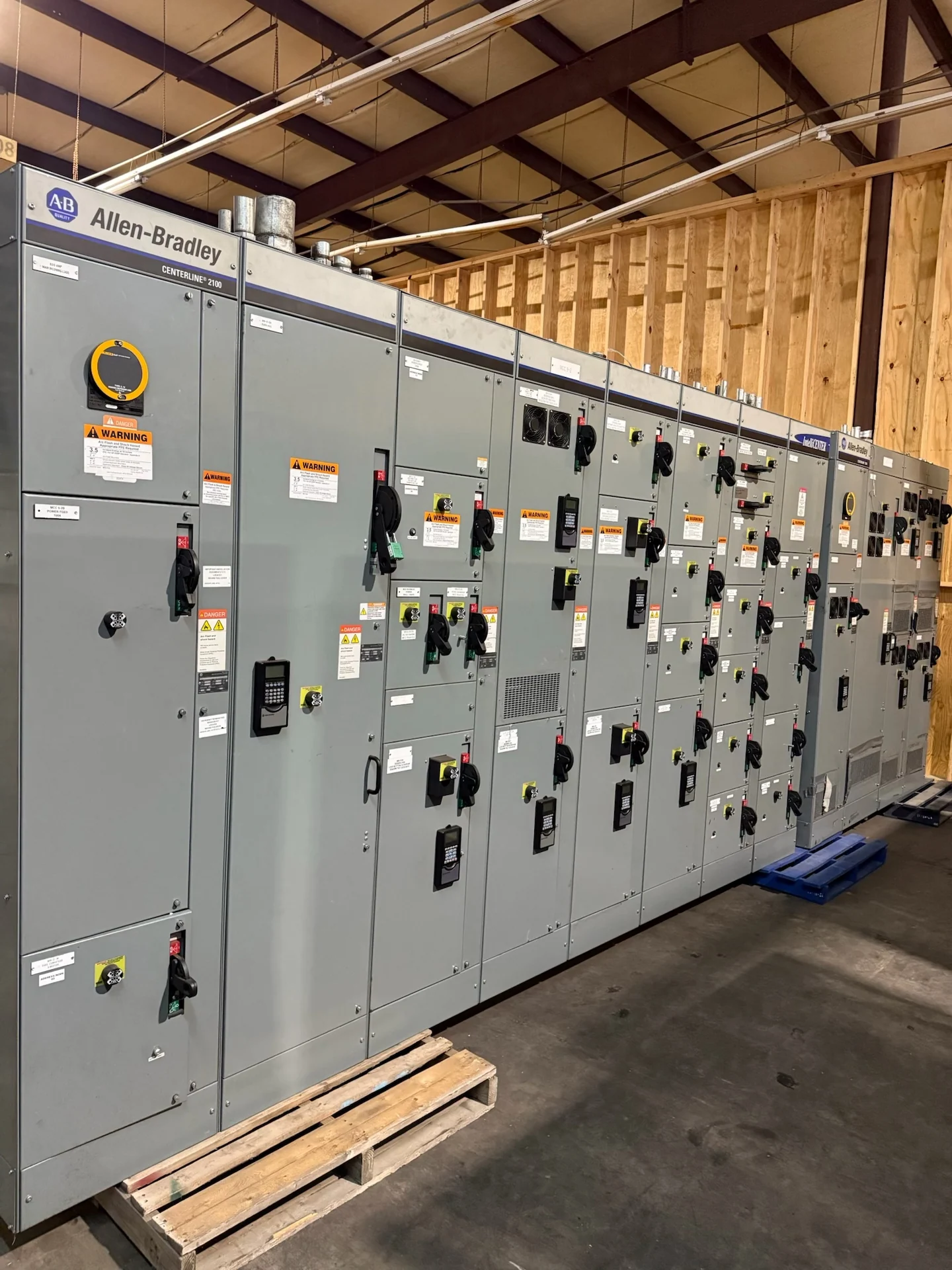
Planning Louisville Data-Center Distribution
A Louisville data-center project begins with the electrical architecture, not a generic equipment size. Define incoming utility sources, transformer interfaces, generator-backed buses, UPS boundaries, critical and noncritical loads, and the operating states the facility must support. Switchgear Builders manufactures new custom switchgear in the United States, using American components and shipping nationwide. For a Kentucky project, the useful starting package includes the one-line diagram, voltage and phase information, available fault current, continuous load calculations, grounding method, room dimensions, cable-entry direction, and the engineer’s sequence of operation. Those inputs let a manufacturer develop equipment around the actual distribution path rather than forcing an unsuitable standard arrangement.
Redundant Sources and Bus Arrangements
Redundancy should be described as an operating strategy with defined dependencies, not simply as a second feeder. Review whether sources are physically independent, how mains and ties are interlocked, which buses can be energized during maintenance, and whether generator capacity is allocated by load group or by a broader facility operating mode. A main-tie-main or related arrangement may look appropriate on a preliminary diagram, yet its switching sequence, transition behavior, protection settings, and control-power sources require project engineering. Ask the design team to identify prohibited paralleling conditions, permitted transfer states, manual overrides, and the indications operators need before custom fabrication begins.
Generator Interfaces and Backup Distribution
Generator interface details affect both the switchgear lineup and the surrounding controls. Identify generator output voltage, grounding and bonding approach, breaker or switching duties, synchronization requirements if applicable, emergency-load priorities, and the signals exchanged with transfer equipment or a supervisory system. The equipment design should show how normal and alternate sources are isolated, how protective relays or trip units receive dependable inputs, and how operators recognize source status. For a Louisville data-center distribution project, also coordinate generator room routing, feeder lengths, cable terminations, ventilation-related equipment interfaces, and maintenance access with the electrical contractor and consulting engineer.
Maintenance Access and Physical Coordination
Maintainability is a physical design requirement as much as an electrical one. Confirm the lineup footprint, working clearances, door swings, removable-device travel, lifting path, floor loading, cable bend space, and the route from receiving to the electrical room. Separate normal operating access from the space needed to withdraw or service equipment, and account for barriers, partitions, overhead obstructions, and future sections. A manufacturer quote should identify shipping splits, approximate section dimensions and weights when available for the defined design, lifting provisions, and receiving responsibilities without assuming that a Louisville site has a particular access condition.
Protective Coordination for Critical Loads
Protective coordination connects the switchgear specification to the complete data-center power study. Provide utility fault information, transformer impedance, generator subtransient data when applicable, feeder conductor details, downstream breaker data, and the desired study boundaries. Engineers can then review short-circuit duty, interrupting ratings, time-current relationships, ground-fault behavior, arc-flash inputs, and selective coordination objectives where required by the project. Settings are not a substitute for equipment ratings, and a manufacturer should not guess them from a city or facility type. Final device selection, trip settings, relay logic, and labeling remain subject to the responsible electrical engineer’s review and applicable project requirements.
Submittals, Verification, and Nationwide Delivery
Before ordering new switchgear, align the quote with the approved one-line diagram, elevations, wiring diagrams, device schedules, control narratives, terminal plans, and test-document expectations. Confirm whether the project calls for switchgear, switchboards, transfer equipment, or a combination; these terms describe different equipment and should not be treated as interchangeable. If UL 891 may apply to a particular switchboard assembly, its applicability and any project-specific listing or capability must be confirmed for that design. Switchgear Builders can coordinate a custom U.S.-built equipment package and nationwide shipping, while the project team confirms site readiness, freight terms, unloading, rigging, installation, and acceptance responsibilities.