Start with the Louisville Service Profile
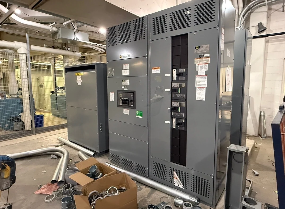
A service-entrance switchboard for a Louisville, Kentucky commercial or industrial project should begin with the electrical service profile, not with a preferred enclosure size or device brand. The design team should identify nominal voltage, phase and wire arrangement, service frequency, grounding method, utility source, and whether the equipment is intended for a new service or a coordinated facility expansion. The one-line diagram should show the service point, transformer relationship, main disconnecting means, feeder circuits, alternate sources if any, and downstream distribution. Those inputs let an American manufacturer build new switchboards custom to specification, using American components and coordinating the equipment package for nationwide shipment. Local utility review and the project engineer remain the authorities for Louisville-specific service requirements.
Coordinate Utility Metering Before Layout
Utility metering can affect the switchboard's compartments, instrument-transformer provisions, conductor routing, access, and the boundary between utility-owned and customer-owned equipment. Before requesting a manufacturer quote, obtain the applicable utility metering information for the Louisville site and identify meter type, socket or compartment arrangement, CT requirements, test-switch provisions, sealing expectations, and space reserved for utility access. Do not assume that a familiar arrangement will be accepted on every service. A coordinated submittal should distinguish utility requirements from owner metering, building automation, and revenue-monitoring requests so each device has a defined location, wiring path, and responsible reviewer.
Define Disconnecting Means and Service Arrangement
The main disconnecting means should be described by its function and operating arrangement, including the number of service disconnects, main-device type, available spaces, emergency or standby source interfaces, and the intended sequence for isolation. The equipment schedule should identify whether feeder protection is integral to the switchboard, what compartments require physical access, and how labels, terminals, and control wiring will be handled. For a multi-tenant commercial building, service sections may need clear separation between tenant distribution and common loads; for an industrial facility, process feeders and maintenance isolation may drive a different arrangement. The engineer of record should resolve grounding, bonding, working-space, and local inspection questions before fabrication.
Calculate Fault Duty and Feeder Requirements
Available fault current is a fundamental input for selecting the main device, feeder protective devices, bus construction, and the assembly's applicable short-circuit rating. Provide the utility contribution, transformer data, conductor information, motor contribution where relevant, generator or inverter sources, and the point at which the calculation applies. Feeder schedules should include circuit identification, calculated load, continuous-load treatment, conductor and termination requirements, protective-device characteristics, and spare or future provisions. A manufacturer can then review the requested service-entrance switchboard configuration against the project data rather than infer ratings from a city, building type, or nominal service description. Protection coordination and arc-flash studies should be completed by qualified parties using the final system model.
Fit the Enclosure to the Electrical Room
Physical planning is as important as the electrical schedule. Confirm available wall length, section depths, bus orientation, cable-entry direction, rear or front access, working clearances, ventilation needs, door swing, removable panels, housekeeping pads, and the route from the receiving point to the electrical room. Louisville projects may involve new construction, renovation, or constrained industrial spaces, so the shipment and installation plan should identify turning limits, doorway dimensions, floor loading, lifting points, and any sections that must be shipped separately. Provide room drawings and interface dimensions early; a custom manufacturer can use them to develop an enclosure layout for review before material is fabricated.
Prepare a Complete Manufacturer Quote Package
A useful request for new service-entrance switchboards should include the one-line diagram, load and feeder schedules, utility correspondence, fault-current study, equipment location, environmental conditions, preferred component architecture, metering details, control requirements, dimensions, shipping destination, and documentation expectations. State which items are mandatory and which remain open for engineering review. Ask the manufacturer to identify assumptions, exclusions, required approvals, and information still needed before a final design is released. Switchgear Builders manufactures and supplies new electrical switchgear in the United States, builds custom to specification, uses American components, and ships nationwide; project-specific applicability of UL 891 and any requested listing or verification must be confirmed for the particular assembly rather than assumed from the project location.