Plan the Maryland Electrical Expansion Around the Actual System
A Maryland facility expansion can change the distribution system well beyond the addition of a few feeders. Start with the utility service arrangement, nominal voltage, phase and wire configuration, grounding method, calculated demand, available fault current, and the loads that the new electrical distribution must serve. A current one-line diagram, panel schedules, site conditions, and the planned operating sequence give a manufacturer a practical basis for discussing new switchgear. Switchgear Builders manufactures custom new electrical switchgear in the United States, using American components and shipping nationwide; final equipment scope remains specific to the project and its engineering requirements.
Coordinate Existing Equipment Interfaces Before Fabrication
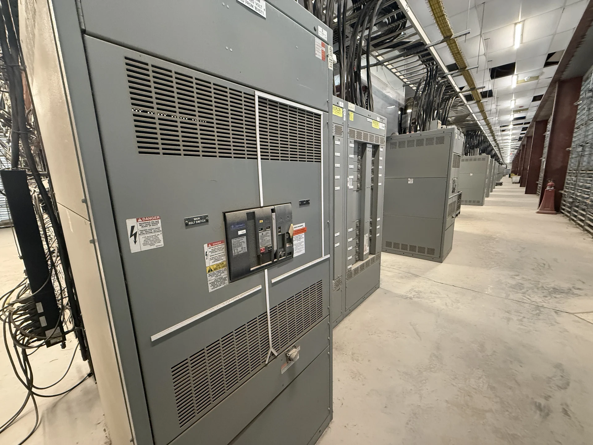
Expansion equipment must connect cleanly to the distribution assets already serving a Maryland site. Gather enclosure dimensions, bus or cable entry locations, feeder names, protective-device information, termination details, grounding connections, control voltages, metering needs, and photographs or field measurements that can be confirmed by qualified personnel. The design team should identify whether the new lineup is adjacent to, fed from, or intended to coordinate with existing equipment, while the installer confirms access and connection methods. Interface drawings and approved submittals help expose mismatched dimensions or sequence assumptions before fabrication begins.
Account for Load Growth and Feeder Protection
A useful Maryland switchgear specification distinguishes today's calculated load from planned expansion capacity. Identify continuous loads, motor starting characteristics, transformer feeders, process equipment, emergency or standby sources, and any future circuits that affect lineup space or bus requirements. Engineers should review available fault current, interrupting or withstand duties as applicable, selective coordination, arc-flash study inputs, and protective settings across upstream and downstream devices. Extra sections or spare spaces may support future work, but they also affect footprint, cost, heat management, and the installation plan, so each allowance should have a defined purpose.
Design Around Outage Windows and Construction Phases
Facility expansion often requires maintaining operations while new feeders are installed, tested, and connected. Establish which loads can be interrupted, whether temporary power or staged cutovers are part of the electrical plan, who controls switching, and what acceptance checks precede energization. A phased lineup, shipping split, cable schedule, and clearly marked termination points can simplify coordination, but these choices depend on the site engineer, electrical contractor, owner, and authority requirements. Provide the manufacturer with the target sequence and constraints early so drawings address installation interfaces rather than treating delivery as the end of planning.
Verify Room Space, Access, and Maryland Site Conditions
Available space is more than the equipment footprint. Confirm working clearances, door swings, maintenance access, cable bending space, ventilation, housekeeping pads or anchorage interfaces, turning paths, loading conditions, and the route from receiving to the electrical room. Indoor or outdoor placement, moisture, dust, corrosive exposure, temperature, and enclosure requirements should be stated for the actual site rather than inferred from the state location. A dimensioned room plan and equipment elevation allow the project team to evaluate whether a custom new switchgear lineup can be moved, installed, connected, and serviced as intended. For Maryland projects, also map whether the expansion serves a coastal, urban, or inland site only insofar as those conditions change the equipment environment and logistics. Identify county or municipal review responsibilities, utility interface requirements, and the installer’s preferred cable terminations before drawings are finalized. If an addition crosses an occupied electrical room, record shutdown boundaries and temporary barriers on the construction plan. For a feeder extension, note transformer locations, conductor routing, and spare conduit paths so the lineup, terminations, and future work remain coordinated. These details give the quote a usable field context without substituting for the engineer’s stamped design or the authority having jurisdiction.
Request a Complete Manufacturer Quote and Delivery Plan
For a Maryland electrical distribution inquiry, include the project location, one-line diagram, ratings, lineup dimensions or constraints, feeder schedule, control and metering requirements, drawings requested, testing expectations, shipping destination, receiving limitations, and the responsible engineering and installation contacts. Ask the manufacturer to identify included components, exclusions, shipping sections, lifting provisions, documentation, and project-specific assumptions. Switchgear Builders can discuss custom-built new equipment and nationwide shipping from the information supplied; availability, transit estimates, applicable standards, and any certification or listing requirement must be confirmed for the particular project.