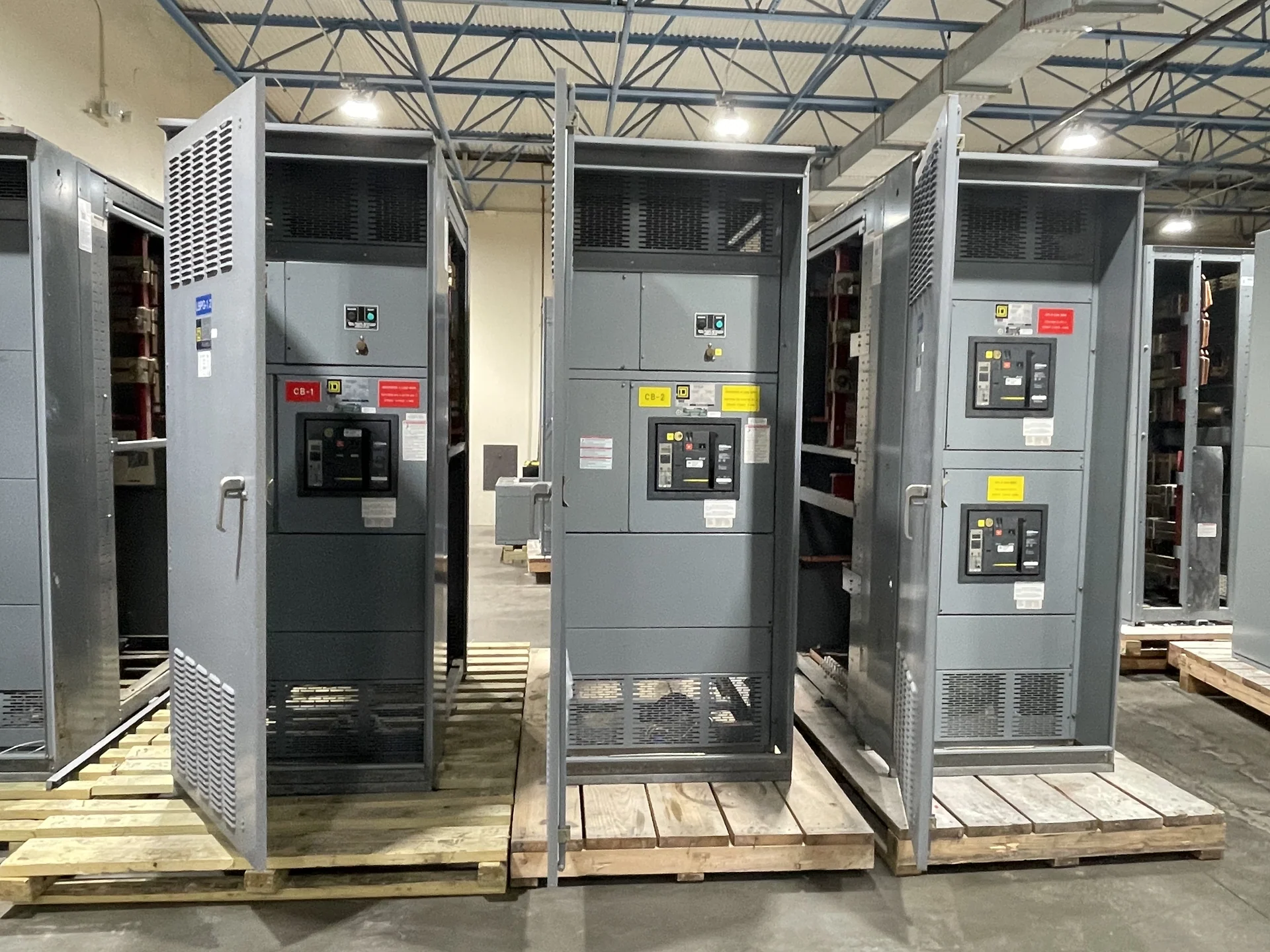
Start with the Baltimore Facility Electrical Basis
A Baltimore industrial facility needs a medium-voltage switchgear specification grounded in the actual distribution system, not just a product label. Begin with the utility service arrangement, nominal system voltage, frequency, phase configuration, grounding method, incoming conductors, transformer connections, and the feeder loads the lineup must serve. Site conditions such as indoor or outdoor placement, available room dimensions, cable-entry direction, environmental exposure, access route, and planned expansion also shape the equipment. Switchgear Builders manufactures new electrical switchgear in the United States, builds custom to project requirements, uses American components, and supplies equipment with nationwide shipping. A useful inquiry should distinguish confirmed design inputs from assumptions awaiting the engineer, utility, or authority having jurisdiction.
Define Voltage Class and Fault Duty
Voltage class should be selected from the system's operating conditions and the equipment duty, rather than inferred from a facility name or transformer size. The design team should identify nominal voltage, maximum system voltage where applicable, insulation requirements, grounding arrangement, and the relationship between the switchgear and connected transformers. Available fault current at the proposed lineup is equally important; ask the electrical engineer to provide the study basis, source contribution, and required short-circuit withstand or interrupting values for each device. These inputs help separate feeder protection needs from enclosure and bus requirements, while avoiding an assumption that a standard lineup will fit every industrial feeder application.
Coordinate Transformer Connections and Feeders
Transformer connections deserve a dedicated review because the switchgear interface affects incoming cable terminations, switching, protection, grounding, and maintenance access. Document each transformer primary connection, expected inrush considerations, secondary relationship, neutral or grounding arrangement, and whether feeders are radial, looped, or tied through another source. For an industrial facility, list motors, process loads, harmonics-sensitive equipment, and any generation or energy-storage interface that could influence coordination. A custom manufacturer quote becomes more useful when the one-line diagram, transformer data, feeder schedule, physical termination details, and operating sequence are submitted together instead of treating the switchgear as an isolated enclosure.
Plan Protective Relaying and Interlocking
Protective relaying should follow the engineer's coordination study and the facility's operating philosophy. Identify the functions required for the incoming source, transformer feeders, bus sections, and downstream circuits, then document instrument-transformer information, relay inputs, trip circuits, control power, communications, and alarm points as applicable. If a main-tie-main or alternate-source arrangement is contemplated, describe the permitted switching sequence and the interlocks that prevent an unsafe or unintended operating condition. Relay settings, arc-flash study inputs, and utility requirements remain project-specific; the manufacturer can build to approved drawings and component selections, but those engineering decisions must be defined and reviewed by qualified parties.
Account for Baltimore Installation Conditions
A Baltimore project should address the actual installation environment and delivery path early. Confirm whether the equipment will be indoors, outdoors, in a process area, or in a dedicated electrical room; then document enclosure expectations, corrosion or moisture exposure, ambient conditions, ventilation, working clearances, seismic or structural requirements if specified, and anchorage interfaces. The installer should verify doors, elevators, loading areas, rigging points, floor openings, cable trenches, and the order in which shipping sections can enter the facility. These details affect lineup dimensions, shipping splits, lifting provisions, and field connections, even when the electrical one-line remains unchanged.
Prepare a Complete New-Equipment Inquiry
For a manufacturer quote, send the project location, one-line diagram, voltage and frequency, grounding method, continuous-current requirements, fault-duty information, feeder count, transformer data, protective-relay scope, control voltage, metering needs, enclosure conditions, dimensions, cable-entry preferences, drawings, inspection expectations, and shipping destination. State which requirements are mandatory and which are alternatives so comparable equipment options can be evaluated. Switchgear Builders can manufacture new custom equipment for the specified project and arrange nationwide shipping; project-specific component selection, drawings, testing, delivery estimates, and any applicable standard or listing requirement must be confirmed during engineering and quotation.