Start with the Minneapolis Site and Process Loads
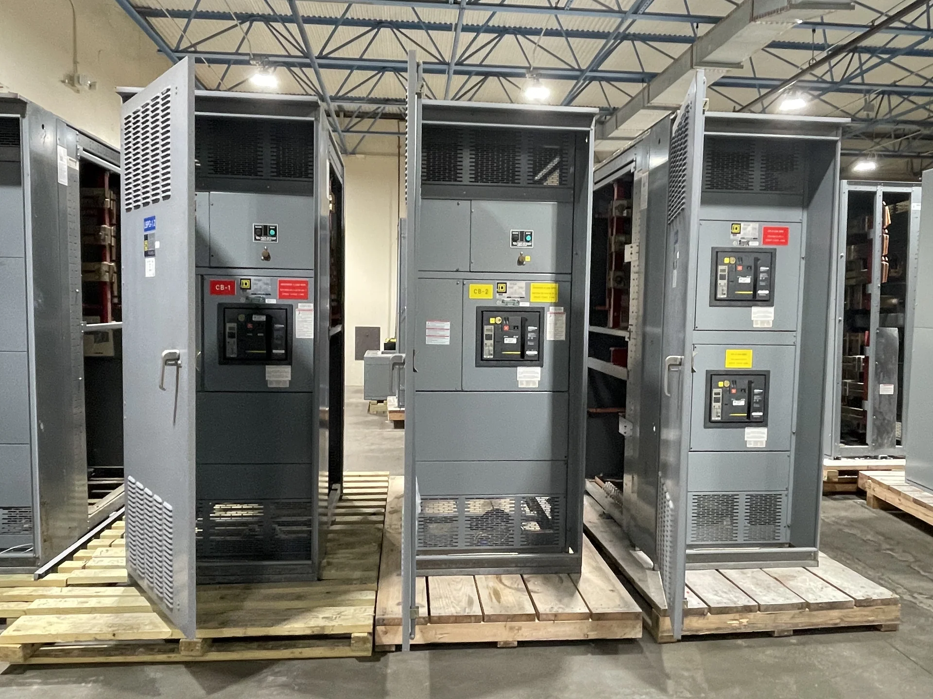
A Minneapolis electrical distribution project for a water or wastewater facility begins with the process, not a catalog label. Identify incoming service characteristics, available fault current, feeder distances, pump horsepower, duty cycles, motor quantities, and which loads must remain available during planned maintenance or a source interruption. The equipment package may include motor control centers for water treatment pumps and process equipment, feeder sections, control power, metering, and interfaces to supervisory controls. A clear one-line diagram and load schedule let the manufacturer distinguish continuous loads from starting demand, reserve capacity from required capacity, and process interlocks from ordinary operator controls. Site elevation, room dimensions, access paths, and installation sequence also belong in the inquiry because a practical lineup must fit both the electrical design and the facility’s construction constraints.
Coordinate Motor Starting and Protection
Motor starting is a system question involving voltage drop, source strength, acceleration time, protective-device settings, and the mechanical behavior of each pump. Across-the-line starters can be straightforward for suitable motors, while reduced-voltage starters or variable frequency drives may be considered when starting current, speed control, soft acceleration, or process regulation makes them useful. The selected approach should follow the engineer’s study and the pump manufacturer’s requirements rather than a generic preference. For each motor, provide horsepower, voltage, phase, frequency, full-load current, service factor, starting method, overload requirements, and any locked-rotor or coordination information available. The switchgear builder can then lay out starters, breakers or fuses, disconnecting means, control transformers, terminals, and separation needs around the actual sequence of operation.
Evaluate Drives, Heat, and Harmonics
Variable frequency drives can support flow control and energy management, but they change the electrical and physical design of a lineup. A drive schedule should identify motor ratings, commanded speed range, bypass expectations if any, input protection, control signals, communications, and fault-reset logic. Heat dissipation matters because drive losses can affect enclosure temperature and room conditions; ventilation or other thermal provisions must be selected from project data. Harmonic current, power factor, grounding, cable length, and electromagnetic compatibility should be reviewed by the responsible electrical team. When a Minneapolis treatment facility combines drives with across-the-line motors, instrumentation, and sensitive controls, segregation, shielding, bonding, and cable routing deserve early attention. These decisions affect enclosure dimensions, wireway space, feeder sizing, and the documentation supplied for installation and commissioning.
Design for Water-Treatment Conditions
Water and wastewater environments can expose electrical assemblies to moisture, condensation, chemicals, washdown, corrosion, and temperature swings, but the correct enclosure and materials depend on the exact room and process area. Define whether the equipment is indoors or outdoors, the installation location relative to wet processes, expected ambient temperature, cleaning methods, corrosive agents, elevation above finished floor, and required enclosure type. Minnesota projects may also require careful coordination around winter construction, exterior equipment exposure, and building heating, yet those conditions should be documented rather than assumed from the city name. The design team should verify clearances, cable-entry direction, drain or condensation provisions, anchorage, grounding and bonding, and access for service. A manufacturer can build to the approved requirements, while the project engineer and installer confirm that the selected assembly suits the site and governing requirements.
Define Controls and Operating Sequences
Pump control is often where a technically adequate power lineup becomes either useful or difficult to operate. Describe local and remote control stations, automatic lead-lag rotation, level or pressure inputs, permissives, alarm contacts, emergency stops, interlocks, HOA switch behavior, communication networks, and what happens after a power restoration. Identify whether the plant control system expects dry contacts, analog signals, Ethernet-based communications, or another interface, and establish terminal numbering and point lists before wiring is finalized. The equipment specification should also address control voltage, spare terminals, wire markers, device labeling, and the boundary between manufacturer-supplied wiring and field wiring. A written sequence of operation helps reviewers test the intended behavior without guessing how a pump, starter, drive, bypass, and upstream protective device interact.
Prepare a Manufacturer-Built Equipment Inquiry
Customers seeking Minneapolis switchgear or motor control centers can request a useful proposal by sending the one-line diagram, load and motor schedules, control narrative, floor plan, available fault-current data, environmental information, utility requirements, and applicable project specifications. Include desired lineup dimensions, shipping destination, receiving limitations, lifting or rigging constraints, documentation expectations, and the names of reviewing parties. Switchgear Builders manufactures new electrical switchgear in the United States, builds custom equipment to specification with American components, and supplies projects with nationwide shipping; project-specific scope, component details, applicability of standards, and delivery arrangements should be confirmed during quotation. If a switchboard assembly may fall within UL 891, the project team must confirm that standard’s applicability and any required listing or verification for the particular design rather than assuming it.