Start with the Critical-Load Map
A Minneapolis project should begin by identifying which loads require automatic source transfer and which can remain on normal distribution. List each critical load, its operating voltage, phase, estimated starting demand, steady-state demand, and tolerance for interruption. Hospitals, pump systems, life-safety support, communications, process controls, and data equipment may have different continuity objectives, so a single transfer strategy should not be assumed. Mark the normal source, alternate source, downstream distribution point, and any required bypass or isolation arrangement on the one-line diagram. Note whether loads can be shed, sequenced, or restored in groups after an outage. This information gives the manufacturer a disciplined basis for a new automatic transfer switch package custom to the project rather than a generic selection.
Define Sources, Capacity, and Transfer Sequence
Source information determines whether an automatic transfer switch can perform the intended operation. Provide the normal-service source, generator or alternate-source details, available capacity, voltage, frequency, phase arrangement, grounding method, and protective-device information. Then describe the operating sequence: normal-to-emergency initiation, engine start signaling, source-available sensing, transfer delay, retransfer delay, cooldown signaling, and behavior after a failed source. Some projects need staged transfers or priority groups instead of one simultaneous action. Identify reset behavior, alarm contacts, remote indications, and whether maintenance personnel need a local test mode. For Minneapolis facilities, winter conditions and site operating procedures may also influence generator placement, maintenance access, and control-panel environment; those factors belong in the project requirements, not in an assumed standard configuration.
Coordinate Protection and Distribution Interfaces
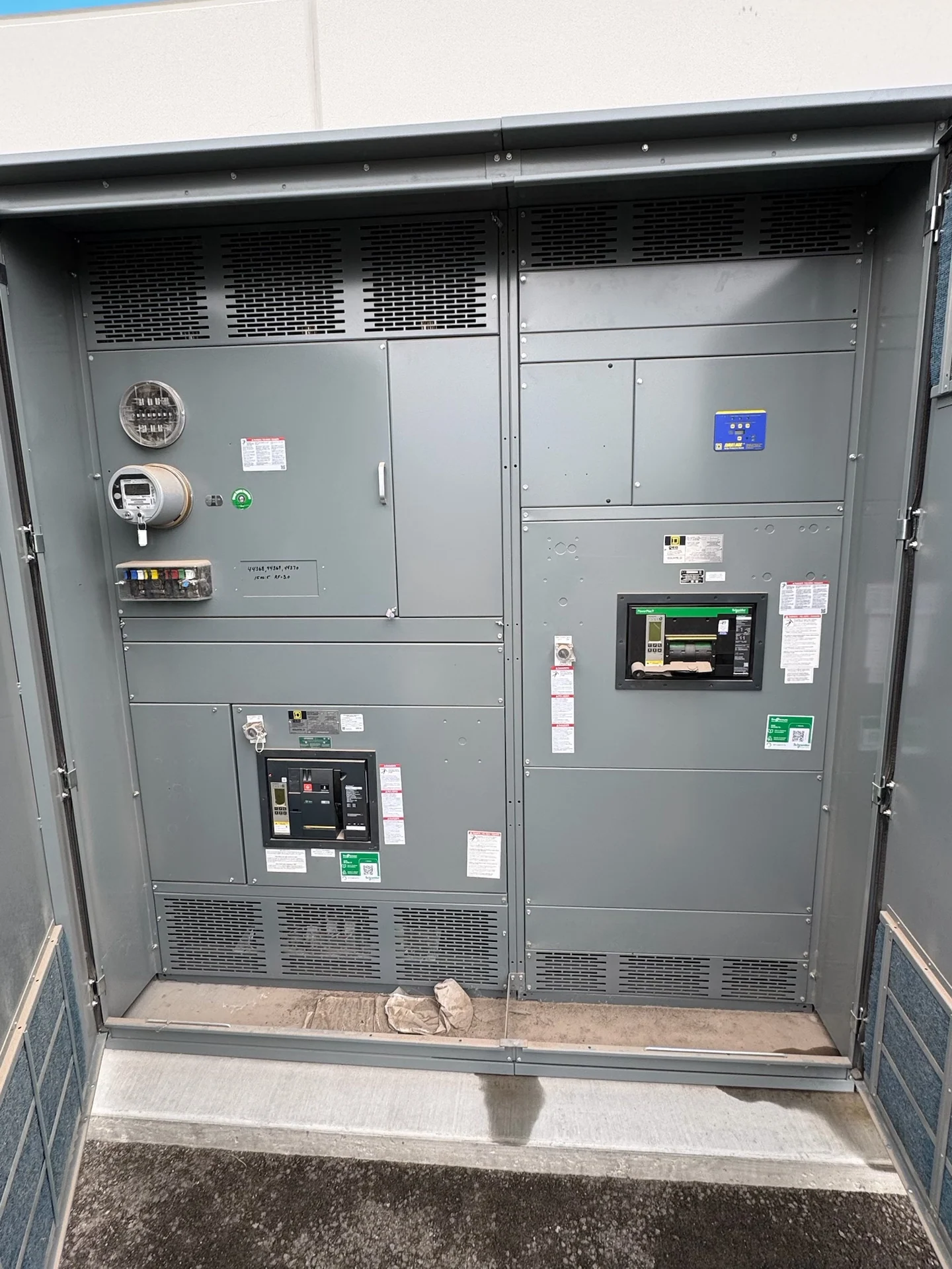
Transfer equipment sits between sources and loads, so its ratings and controls must coordinate with upstream and downstream distribution. Supply available fault current, main and feeder protective-device data, conductor information, and selective-coordination objectives for engineering review. Confirm whether the switch is intended for service equipment, feeder use, or a generator connection, and identify neutral switching and grounding requirements with the electrical engineer. The enclosure, terminals, cable entry, ventilation, and working clearances must fit the Minneapolis installation space and the route used to bring the assembly into place. Account for connection torque information, phase identification, control-voltage arrangements, and interface points with the generator controller or building-management system. Project-specific standards, inspection expectations, and the applicability of UL 891 or another requirement must be confirmed before the design is finalized.
Plan Maintenance, Testing, and Access
Critical-load continuity depends on more than the transfer command. Define how operators will test source sensing, start signaling, transfer timing, retransfer behavior, alarms, manual controls, and failed-source responses without creating an unacceptable interruption. Show clearances for inspection, cable termination, control access, and any bypass-isolation equipment that the design requires. Identify who will witness factory checks, what results must be recorded, and which field tests belong to the installer or commissioning team. Consider how operators will document test dates, return the equipment to automatic operation, and communicate an unavailable alternate source. A new switchgear or transfer-equipment package can include drawings, wiring identification, settings information, and agreed test documentation, but acceptance criteria should be written for this project and reviewed by qualified electrical personnel.
Prepare a Manufacturer Quote Request
A useful request for automatic transfer switches for critical loads should include the one-line diagram, load schedule, source details, transfer sequence, enclosure environment, dimensions or space limits, cable-entry direction, required controls, communication points, documentation list, destination, and shipping constraints. Identify the Minneapolis delivery site, receiving contact, and access restrictions for freight planning. Include the requested quantity, equipment naming convention, drawing review process, inspection or witness expectations, and who will coordinate field installation. Switchgear Builders manufactures new electrical equipment in the United States, builds custom to specification with American components, and ships nationwide; project scope still governs configuration, component selection, documentation, and any applicable standard. Ask for a written scope that separates equipment, testing, freight, field work, and owner responsibilities so the electrical team can compare the proposal accurately.