Start with the Saint Paul Process Load
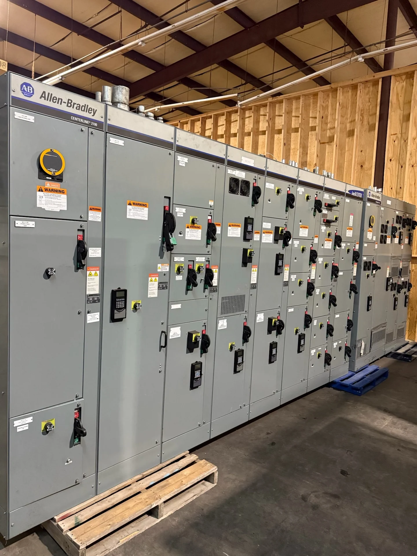
An industrial motor control center for a Saint Paul, Minnesota facility should begin with the process it must operate, not with a preferred enclosure or starter brand. List pumps, conveyors, fans, compressors, mixers, and other motor-driven loads, then identify each motor's voltage, phase, horsepower, full-load current, starting method, duty, and operating sequence. A useful equipment definition also separates continuously running motors from intermittent or critical loads, records local ambient conditions, and identifies which controls must communicate with a supervisory system. Switchgear Builders manufactures new custom electrical equipment in the United States, using American components and supplying projects nationwide; the final arrangement remains subject to project engineering and the installation requirements at the Saint Paul site.
Choose Starters, Drives, and Feeder Protection
Motor control centers can combine across-the-line starters, reduced-voltage starting methods, variable frequency drives, feeder disconnects, and protective devices, but each choice changes space, heat, wiring, maintenance, and coordination needs. Across-the-line starting may simplify a small motor circuit while imposing a higher inrush current; a drive can support speed control but introduces thermal, harmonic, grounding, and motor-cable questions. Specify overload protection, short-circuit protection, disconnecting means, control power, bypass requirements, and fault-duty information for every section. For industrial pumps and conveyors, compare the operating sequence and consequence of a trip rather than selecting devices by motor size alone.
Define the Control Interface Before Fabrication
A clear control narrative prevents an industrial motor control center from becoming a collection of disconnected buckets. Document permissives, interlocks, emergency-stop behavior, local and remote modes, alarm points, run feedback, fault indication, reset logic, and the sequence for starting or stopping related equipment. Identify whether the interface uses hardwired terminals, network communications, analog signals, or a combination, and coordinate point naming with the controls engineer. Pump systems may require level, pressure, or flow inputs, while conveyors may need permissive chains and jam detection. These details affect control wiring, terminal space, device selection, and the drawings supplied for review.
Coordinate the Physical Layout and Environment
The Saint Paul project team should confirm where the lineup will be installed, how it will enter the building, and how technicians will reach doors, terminals, drives, and protective devices. Provide available room dimensions, working clearances, cable-entry direction, feeder routing, lifting or handling limits, and the relationship to transformers, disconnects, and process machinery. Minnesota seasonal conditions may influence whether equipment is indoors, in a conditioned electrical room, or exposed during portions of installation; enclosure and environmental requirements must therefore be defined from the actual site. Separate power and control routing as required by the design, and reserve space for the specified heat-management and service-access approach.
Build a Complete Quote Package
When requesting project-specific equipment information, send the one-line diagram, motor schedule, control schematic or narrative, available fault-current data, system voltage and frequency, grounding method, enclosure requirements, lineup dimensions, cable-entry preferences, and required metering or communications. Include the facility address for shipping coordination, the desired equipment split, receiving limitations, and the responsibilities of the electrical contractor, controls integrator, and qualified installer. A quote comparison is meaningful only when scope, component assumptions, drawings, testing, documentation, and freight treatment are aligned. Switchgear Builders can review a custom new-equipment inquiry for a Saint Paul application and coordinate nationwide shipment, receiving details, and project contacts.
Review Drawings, Testing, and Delivery Interfaces
Before release, review the lineup elevation, one-line, elementary diagrams, wiring diagrams, terminal schedules, device lists, nameplate information, and network architecture against the approved motor schedule. Confirm that interlocks and control sequences match the process narrative, that feeder and motor protection inputs are available to the responsible engineer, and that installation drawings show usable cable and service interfaces. Establish the project test plan and acceptance records in advance; any standard or listing requirement, including whether UL 891 applies, must be confirmed for the specific assembly. For shipment to Saint Paul, coordinate packaging, lifting points, shipping sections, receiving inspection, storage conditions, and the handoff to qualified installation personnel.