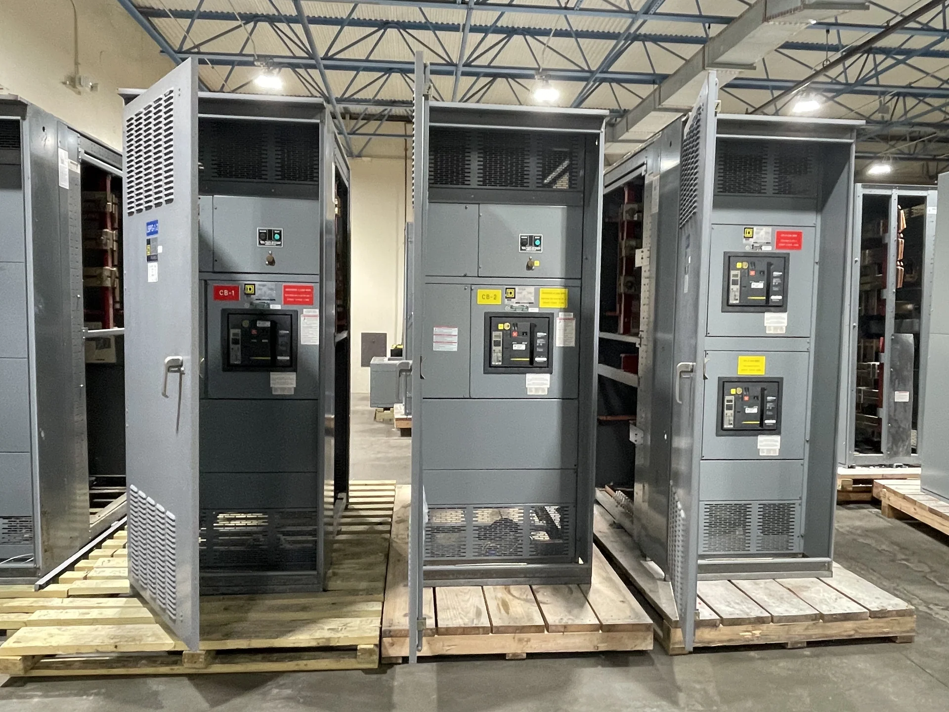
Plan the Feeder Before Selecting Equipment
New York industrial projects often begin with a one-line diagram, a facility load schedule, and a defined utility or generation interface. Those inputs establish whether medium-voltage switchgear is appropriate for incoming service, transformer feeders, process distribution, or multiple downstream lineups. A useful equipment inquiry identifies nominal system voltage, frequency, phase arrangement, grounding method, continuous current, available fault current, and the operating sequence for each source and feeder. Switchgear Builders manufactures new electrical switchgear in the United States, builds custom to specification, uses American components, and supplies equipment with nationwide shipping. The final configuration remains project-specific: the engineer of record, utility, and authority having jurisdiction must confirm the applicable electrical requirements for the New York installation.
Confirm Voltage Class and Transformer Interfaces
Medium-voltage switchgear for industrial facility feeders must be matched to the actual system, not selected from a nominal label alone. Confirm the system voltage, equipment voltage class, insulation coordination, basic impulse insulation level where applicable, short-circuit duty, and the connection arrangement at each transformer. The specification should show cable entry, termination space, phase spacing, grounding provisions, neutral treatment, and any restrictions created by transformer impedance or inrush. If a project uses multiple transformers, document whether feeders operate independently, share a bus, or require a tie with defined interlocking. These details let a manufacturer develop a custom lineup that fits the electrical design rather than forcing field changes after fabrication.
Coordinate Relaying and Fault Duty
Protective relaying should be developed as part of the distribution study, not added after the enclosure layout is complete. Provide relay functions, instrument-transformer ratios, trip and close circuits, control power, communications requirements, breaker or switch operating sequences, and the desired coordination with transformer protection and downstream feeders. Available fault current at each bus affects breaker interrupting capability, bus bracing, grounding, and the assembly short-circuit rating or withstand requirement, as applicable. A New York project may also involve utility review or site-specific interconnection criteria, so the design team should identify who approves settings and what study documents accompany the submittal. Final settings and device selection require qualified engineering review.
Account for Industrial Room and Site Conditions
Physical planning is as important as the single-line diagram for industrial electrical distribution. Share room dimensions, equipment access paths, floor elevations, cable-trench or conduit locations, working clearances, ventilation conditions, environmental exposure, seismic or anchorage criteria when applicable, and the proposed shipping split. Indoor and outdoor arrangements can impose different enclosure, drainage, corrosion, access, and maintenance considerations. Include the transformer location and cable bending radius early, because a lineup that meets electrical ratings may still be impractical to install. For a custom quote, provide drawings, preferred lineup orientation, lifting information, control interfaces, and installation responsibilities so the manufacturer can identify unresolved interfaces before production documentation is finalized.
Build a Clear New York Delivery and Approval Plan
A complete purchase package for New York electrical distribution should define the equipment scope, approved drawings, component requirements, inspection or testing expectations, documentation, destination, freight terms, receiving contact, and site access limitations. Confirm project-specific service and delivery details rather than assuming inventory, a lead time, or a standard shipment arrangement. Switchgear Builders can discuss new custom equipment requirements directly with the project team and coordinate nationwide shipping based on the agreed scope. Before release, reconcile the approved one-line diagram, protection study, dimensional drawing, control schematic, nameplate information, and shipping sections with the installing contractor. This process helps preserve alignment among the manufacturer, engineer, utility, and facility owner.