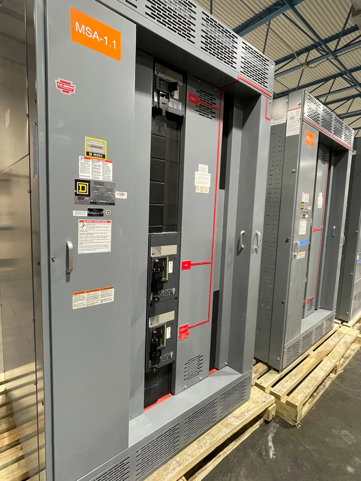
Plan the New York City Distribution Context
A New York City electrical distribution project should begin with the facility's actual load profile, utility service arrangement, available fault current, environmental conditions, and operating priorities rather than with a preferred equipment name. Data centers may require distinct power paths, generator-backed loads, maintenance bypasses, or carefully controlled source transfers. The building structure, delivery route, electrical-room clearances, flood or moisture exposure, and coordination with other trades can affect the switchgear layout. Switchgear Builders manufactures new electrical switchgear in the United States, custom to project specifications, with American components and nationwide shipping. A useful inquiry identifies the site, equipment interfaces, delivery destination, and installation responsibilities.
Define Redundant Sources and Bus Arrangements
Redundancy is a system architecture question, not simply a request for two identical lineups. The design team should document normal sources, standby generators, automatic transfer equipment, bus ties, preferred operating states, and the loads permitted on each path. A main-tie-main arrangement, separate lineups, or another topology may suit different maintenance and fault-containment objectives. Drawings should show whether sources can be paralleled, how interlocks prevent an unintended sequence, and which equipment receives alternate power. Confirm phase, frequency, voltage class, grounding method, continuous current, and short-circuit requirements before a manufacturer develops a custom arrangement.
For data center distribution, resilience also depends on how feeders leave the lineup and how future capacity is reserved. Physical separation may be needed between paths, while cable entry, busway connections, and generator interfaces must remain accessible for installation and service. Ask the engineer to identify single points of failure, required selective coordination, and the consequences of each switching action. The manufacturer can use the approved one-line diagram, load schedule, control narrative, and dimensional constraints to prepare equipment that matches the defined operating sequence instead of assuming that a generic redundant configuration fits the facility.
Coordinate Generator Interfaces
Generator-connected switchgear requires more than a source label on a one-line diagram. The project should state generator ratings, breaker duties, grounding and neutral treatment, synchronization requirements where applicable, transfer logic, load-shed priorities, and the signals exchanged with generator controls or an energy-management system. Protective relays, metering transformers, communication wiring, and control power need defined terminals and locations. Engineers should also establish whether closed-transition operation, momentary interruption, or another transfer sequence is intended. Each choice affects interlocking, protection settings, testing, and the documentation supplied with the new assembly.
Design for Maintenance Access
Maintenance access must be evaluated against the actual room, not just the front elevation of a lineup. Review working clearances, door swings, removable-device travel, cable bending space, lifting paths, shipping sections, and the route from the receiving point to the final electrical room. A data center owner may need planned maintenance on one source while another source remains in service, but that objective depends on the complete distribution design and qualified operating procedures. Include equipment weights, anchorage interfaces, ventilation, lighting, and coordination with fire protection and building systems in the layout review before fabrication.
Review Protective Coordination and Fault Duty
Protective coordination for a New York City project should use the calculated utility and generator fault contributions, transformer data, feeder lengths, protective-device curves, and operating modes that the facility can actually enter. The study team should compare normal-source, generator-source, tie-closed, and maintenance conditions where applicable. Specify interrupting ratings, short-circuit withstand or short-circuit current ratings as applicable, trip-unit functions, relay inputs, and setting documentation from the study rather than selecting devices by amperage alone. Arc-flash analysis, grounding, and equipment labeling should be addressed by the responsible design professionals and applicable project requirements.
Prepare a Complete Manufacturer Inquiry
A complete inquiry helps a manufacturer price and engineer the right new switchgear without avoidable assumptions. Provide the latest one-line diagram, load and short-circuit studies, source information, equipment schedule, control schematic or sequence, enclosure and environmental requirements, dimensions, cable-entry preferences, metering needs, communication points, documentation list, inspection or witness expectations, destination, and site access limitations. If UL 891 may apply to a switchboard assembly, identify that requirement early; its applicability, construction details, and any project-specific listing or capability must be confirmed for the particular equipment. Switchgear Builders can coordinate a custom build and nationwide shipment after the project scope is defined.