Plan the Tennessee Feeder Before Selecting Equipment
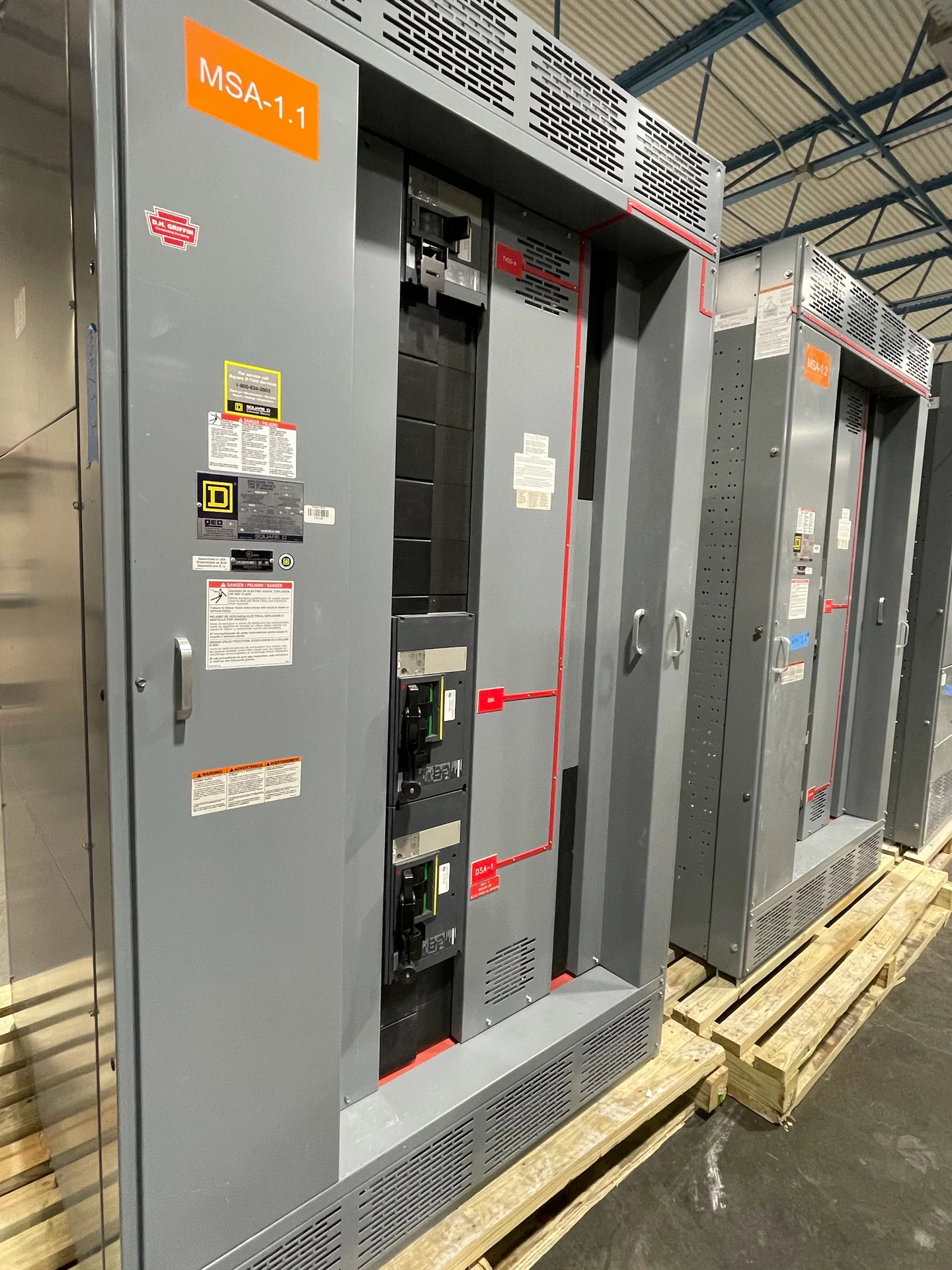
A Tennessee industrial project should begin with the electrical one-line, not a catalog label. Identify each utility or generation source, transformer connection, feeder destination, grounding method, operating voltage, frequency, phase arrangement, and anticipated load profile. Medium-voltage switchgear for industrial facility feeders must be coordinated with the complete distribution system, including transformer impedance, motor starting, emergency sources, and future expansion. Switchgear Builders manufactures new electrical switchgear in the United States, builds custom to specification, uses American components, and ships nationwide. For a Tennessee destination, the quote package should state the site conditions and delivery point while leaving final design decisions to the responsible electrical engineer.
Confirm Voltage Class and Insulation Requirements
Nominal system voltage alone does not complete a medium-voltage switchgear specification. The design team should confirm the equipment voltage class, continuous current, interrupting or withstand duty as applicable, insulation coordination, basic impulse insulation level where relevant, frequency, phase configuration, and grounding arrangement. Transformer primary connections can change cable terminations, phase spacing, neutral treatment, and protection requirements. Outdoor exposure, indoor room conditions, altitude, contamination, temperature, and enclosure needs also affect the design. A Tennessee electrical distribution request is stronger when these inputs are documented alongside the one-line and equipment schedule rather than inferred from a city, county, or facility type.
Coordinate Transformer Connections and Feeder Interfaces
Transformer interfaces deserve a dedicated review because the switchgear, transformer, cable system, and grounding network operate as one electrical path. Provide transformer ratings, primary and secondary voltages, impedance information when available, connection configuration, tap details, neutral and grounding approach, cable quantity and size, termination style, and physical entry direction. Confirm whether the lineup feeds one transformer, multiple transformers, or a tie arrangement, and document the intended isolation and switching sequence. These details guide compartment dimensions, bus arrangement, device selection, and control wiring for a new custom assembly without assuming a particular manufacturer, topology, or site condition.
Develop Protective Relaying and Operating Logic
Protective relaying should be defined from the system study and operating requirements, then translated into a clear equipment schedule. Identify feeder protection functions, instrument transformer requirements, relay inputs and outputs, trip and close circuits, lockout or permissive logic, source interlocks, alarms, local controls, remote communications, and the desired event or metering information. Review time-current coordination across utility, transformer, feeder, and downstream devices so settings can be evaluated against the actual fault study. If a Tennessee industrial facility has parallel sources, generators, or process loads, state the permitted operating states and abnormal conditions explicitly; the manufacturer can then build the specified new switchgear around an engineer-reviewed control scheme.
Evaluate Fault Duty and Documentation
Available fault current is a project input, not a generic regional value. Request the latest utility information, transformer data, conductor lengths and impedances, motor contribution assumptions, source configurations, and study basis used to establish fault duty. Compare the resulting duty with the selected devices, bus, enclosure, grounding path, and required short-circuit or withstand characteristics. The submittal should identify assumptions, ratings, wiring diagrams, terminal details, dimensions, lifting points, and test documentation to be agreed for the project. If a specification references UL 891, first confirm whether that standard applies to the particular assembly and what project-specific listing or verification requirements must be met; do not treat it as automatic for every medium-voltage design.
Coordinate Shipment to a Tennessee Jobsite
Nationwide shipping makes delivery coordination part of the equipment plan even when the manufacturer and jobsite are in different states. Supply the Tennessee destination, receiving hours, access limitations, dock or crane conditions, route constraints known to the project team, packaging expectations, shipping splits, approximate section weights, and required lifting points. Coordinate responsibility for unloading, indoor movement, storage, weather protection, inspection at receipt, and protection against construction damage. Switchgear Builders can prepare new equipment for shipment from the United States, but project-specific availability, freight terms, transit estimates, and receiving responsibilities should be confirmed in the quotation and approved drawings rather than assumed.