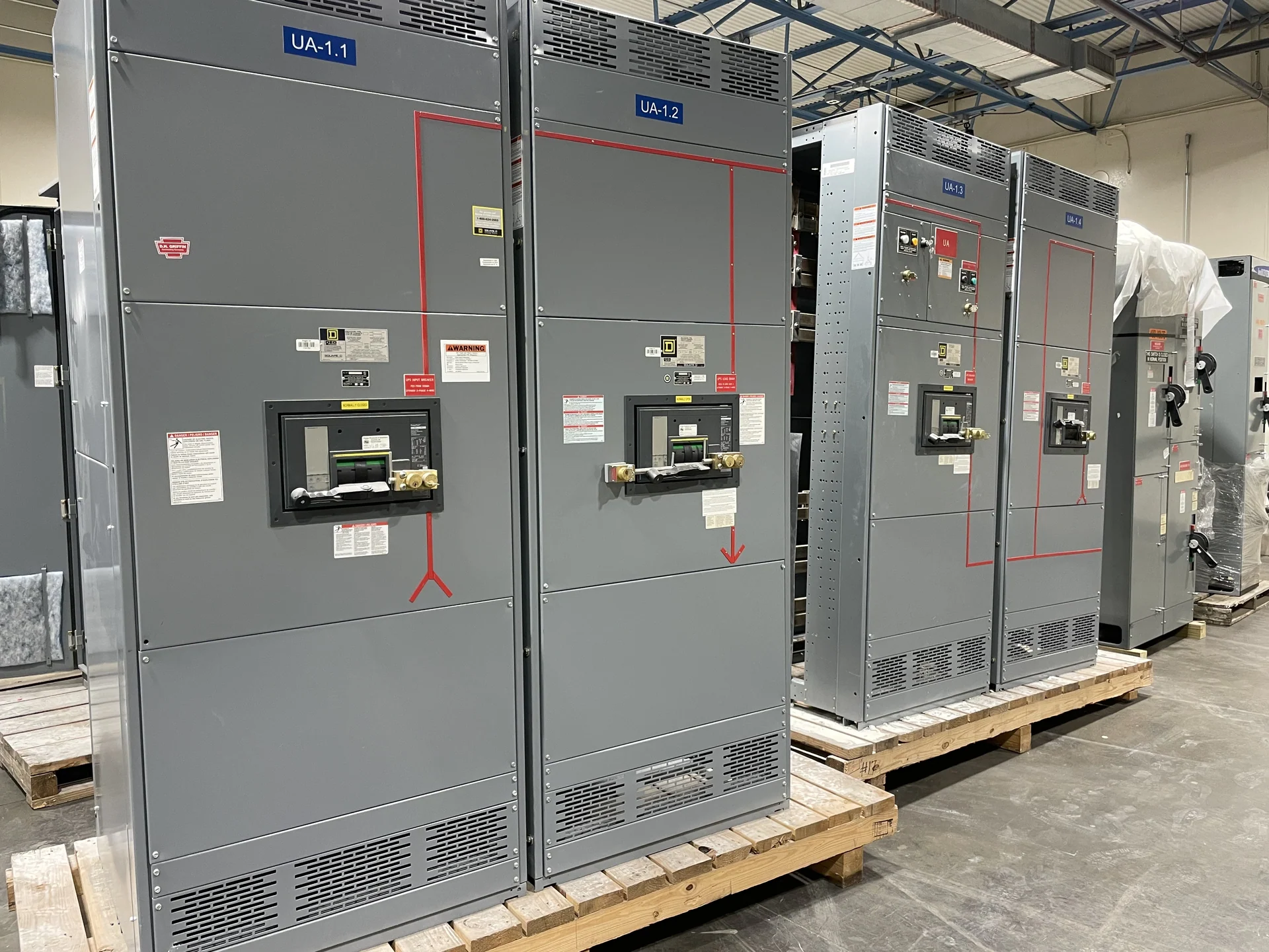
Start with the Nashville Site and Distribution Concept
A Nashville data-center distribution project should begin with the electrical one-line diagram, source arrangement, load schedule, and physical constraints rather than a generic equipment label. Identify utility service points, generator sources, transfer equipment, UPS interfaces, distribution voltages, grounding method, and the loads that require separate power paths. A manufacturer can build new custom switchgear in the United States to those project inputs, using American components and coordinating nationwide shipping. The equipment specification should distinguish normal, emergency, and maintenance operating states so the lineup supports the intended sequence without assuming that every facility has the same topology.
Plan Redundant Power Paths Carefully
Redundancy is an operating design, not simply a second main device. For Nashville electrical distribution serving critical computing loads, document which sources feed each bus, whether bus ties remain open or closed, and how a path is isolated for maintenance. Review single points such as common control power, shared cable routes, interlocking logic, and a single section that could disable both paths. Switchgear dimensions, compartment access, feeder grouping, metering, and control terminals should match the physical and operational separation required by the engineer. A custom build should preserve clear identification of normal and alternate source positions in drawings and equipment labels.
Coordinate Generator Interfaces and Transfer Sequences
Generator distribution requires more than connecting a source to a bus. Define generator breaker functions, source availability signals, synchronizing or paralleling requirements when applicable, neutral and grounding arrangements, load-shed logic, and the relationship between automatic transfer equipment and switchgear controls. Confirm how the system responds to generator start, source failure, retransfer, testing, and a generator that is unavailable. The project team should supply generator data, protective settings, control schematics, and the intended sequence of operation before fabrication. Those inputs let the manufacturer build an assembly whose terminals, devices, and wiring are aligned with the approved control concept rather than guessed from a facility type.
Make Maintenance Access Part of the Layout
Maintenance access affects room planning, equipment arrangement, outage procedures, and the practical value of redundant paths. Provide the available room dimensions, door and route limitations, working clearances, cable entry direction, lifting or handling constraints, and the access needed to inspect and service devices. Consider whether a breaker or control compartment can be reached without crossing an energized path, and identify which functions must remain available during planned work. A Nashville project may have a tight delivery route or phased construction sequence, so shipping splits, shipping dimensions, lifting points, and field-connection boundaries should be resolved with the installer before drawings are finalized.
Review Protection and Fault-Duty Inputs
Protective coordination depends on the complete distribution model, not on switchgear alone. Supply available fault current at each relevant source and bus, transformer impedance, conductor information, device interrupting requirements, time-current data, and proposed protective settings. The engineer can then evaluate selective coordination, short-circuit duty, ground-fault behavior, arc-flash study inputs, and coordination between utility, generator, transfer, UPS, and downstream devices. Ask the manufacturer to reflect approved device selections, trip units, relay interfaces, metering, and control wiring in the submittal package. If UL 891 is identified for a particular assembly, confirm its applicability and any project-specific listing requirements before the design is accepted.
Prepare a Complete Manufacturer Quote Request
A useful request for Nashville switchgear should include the one-line diagram, load and fault studies when available, nominal voltage and frequency, phase and wire configuration, continuous current, short-circuit requirements, enclosure environment, bus material, device schedule, control voltage, communications needs, dimensions, cable entry, metering, labels, testing, drawings, and shipping destination. State which items are by others and which belong in the new equipment package. Switchgear Builders manufactures custom new electrical switchgear in the United States, supplies American components, and ships nationwide; the final scope, documentation, shipping terms, and any schedule estimate must be established for the specific project after technical review.