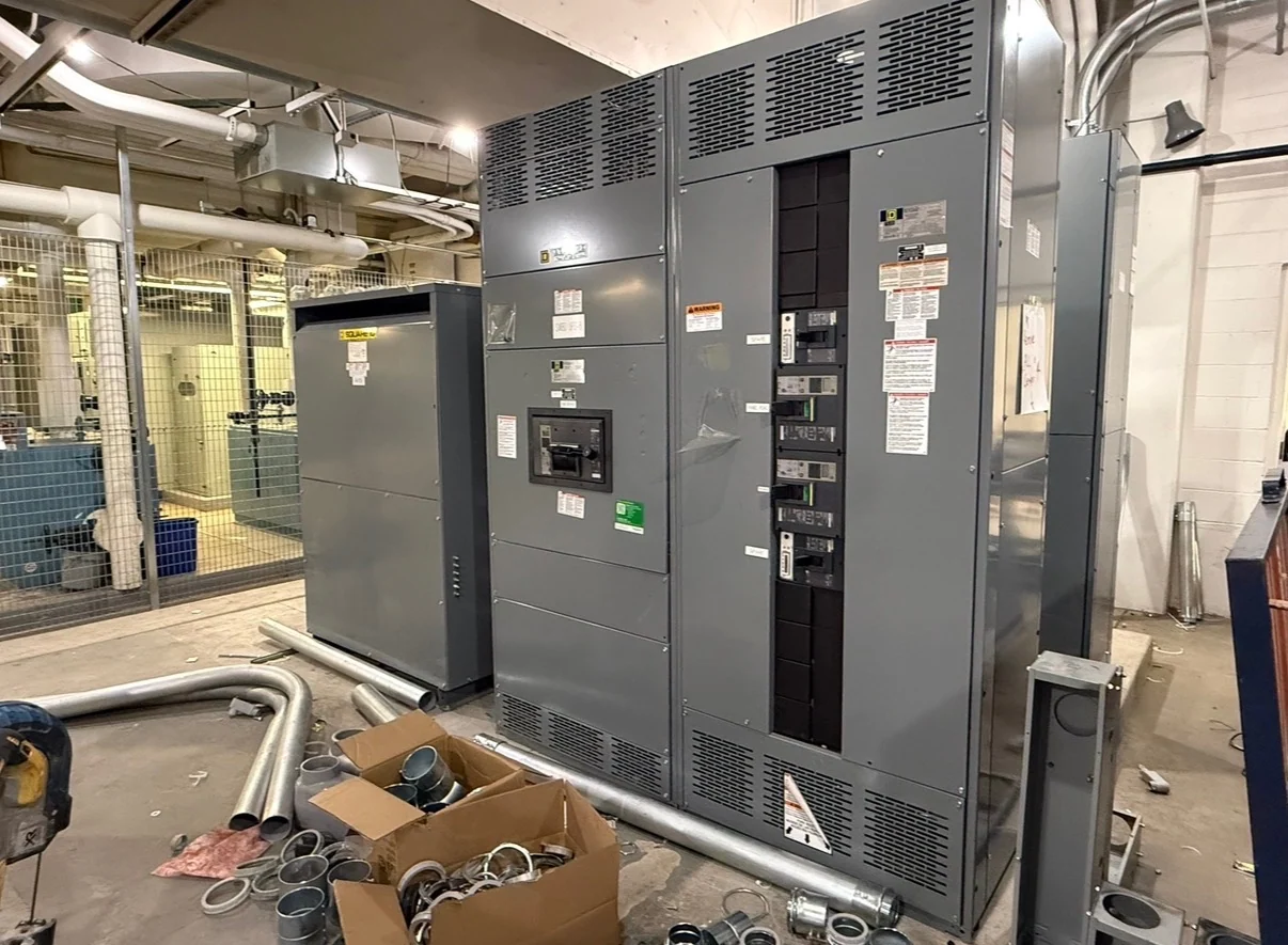
Texas Data Center Distribution Starts With a Clear Electrical Basis
Texas switchgear projects for data centers begin with a documented electrical basis rather than a product label. Define utility service characteristics, nominal voltage, phase and frequency, grounding method, available fault current, continuous loads, motor contributions, and the operating sequence for normal and alternate sources. The design team should map each critical load from service entrance equipment through transformers, switchboards, transfer equipment, uninterruptible power systems, distribution panels, and the final connection. A manufacturer can then develop new custom switchgear around the one-line diagram, physical constraints, control requirements, and American component preferences. Because Texas facilities may have distinct utility, campus, and permitting requirements, the project engineer must confirm applicable local criteria before the equipment scope is finalized.
Source Redundancy and Backup Architecture
Redundancy is useful only when the source arrangement, transfer logic, and maintenance strategy are defined together. A data center owner may evaluate dual utility services, generator-backed buses, main-tie-main lineups, isolated distribution paths, or other architectures selected for the facility’s risk profile. Each choice affects bus segmentation, interlocking, metering, protection, cable entry, and the loads that may be transferred. Ask whether sources can be operated in parallel, whether a tie is normally open, which transfer events are automatic, and how a qualified operator restores the preferred configuration. These answers should appear in the control narrative and one-line documents supplied for a Texas electrical distribution quotation, not remain as assumptions in a device schedule.
Generator Interfaces Require More Than a Feeder Connection
Generator distribution should be coordinated across electrical, controls, mechanical, and commissioning disciplines. The switchgear package may need defined generator feeder ratings, neutral and grounding treatment, source sensing, breaker status, permissive signals, emergency-stop interfaces, synchronization requirements where applicable, and a sequence for starting, transferring, loading, unloading, and returning to normal service. Confirm whether the generator system is a separately derived source and identify the protection and metering responsibilities at every interface. Physical details matter as well: generator cable routes, termination space, lineup sections, lifting provisions, access doors, and room clearances can change the enclosure arrangement. A new custom build should reflect approved drawings and an agreed operating sequence rather than a generic backup-power template.
Maintenance Access Shapes the Lineup
A resilient data center distribution plan accounts for inspection and maintenance without treating accessibility as an afterthought. Review whether breakers or switches are fixed-mounted or removable, where technicians will stand, how equipment sections can be isolated, and how a service task affects redundant paths. Coordinate working clearances, rear or front access, cable bending space, ventilation, overhead obstructions, door swing, and the route for bringing large assemblies into the electrical room. Texas project teams should also document site conditions such as outdoor exposure, temperature range, dust, moisture, and storm-related concerns so enclosure and installation choices receive engineering review. The manufacturer can use those inputs to prepare a practical enclosure layout, shipping split, and connection arrangement for the specified site.
Protective Coordination and Fault-Duty Inputs
Protective coordination connects the data center’s reliability goals to actual device settings and fault-duty decisions. Provide the latest utility fault information, transformer impedances, generator subtransient data when relevant, conductor lengths and sizes, equipment grounding details, and the intended operating states for normal and emergency sources. The engineer can use these inputs to review time-current behavior, selective coordination objectives, interrupting ratings, short-circuit current ratings, bus bracing, and arc-flash study assumptions. Settings should not be selected from nominal amperage alone, and a switchgear quotation should clearly separate supplied device data from field study responsibilities. Any UL 891 requirement, listing path, or related construction criterion must be evaluated and confirmed for the specific switchboard or switchgear project; it should never be presumed from the route or application.
Specify, Build, and Ship New Texas Project Equipment
A useful inquiry for Texas switchgear should include the one-line diagram, load and fault calculations, equipment schedules, site address, indoor or outdoor location, dimensions, elevations, cable entry direction, control schematics, metering needs, communications requirements, preferred American components, required drawings, inspection expectations, and shipping constraints. Switchgear Builders manufactures new electrical switchgear in the United States, builds custom to specification, uses American components, and ships nationwide. Project-specific service scope, component availability, design approvals, freight terms, and delivery details still need confirmation before commitment. During review, compare proposed sections against the approved one-line and control narrative, then coordinate receiving, rigging, installation, field testing, and energization with qualified project professionals.