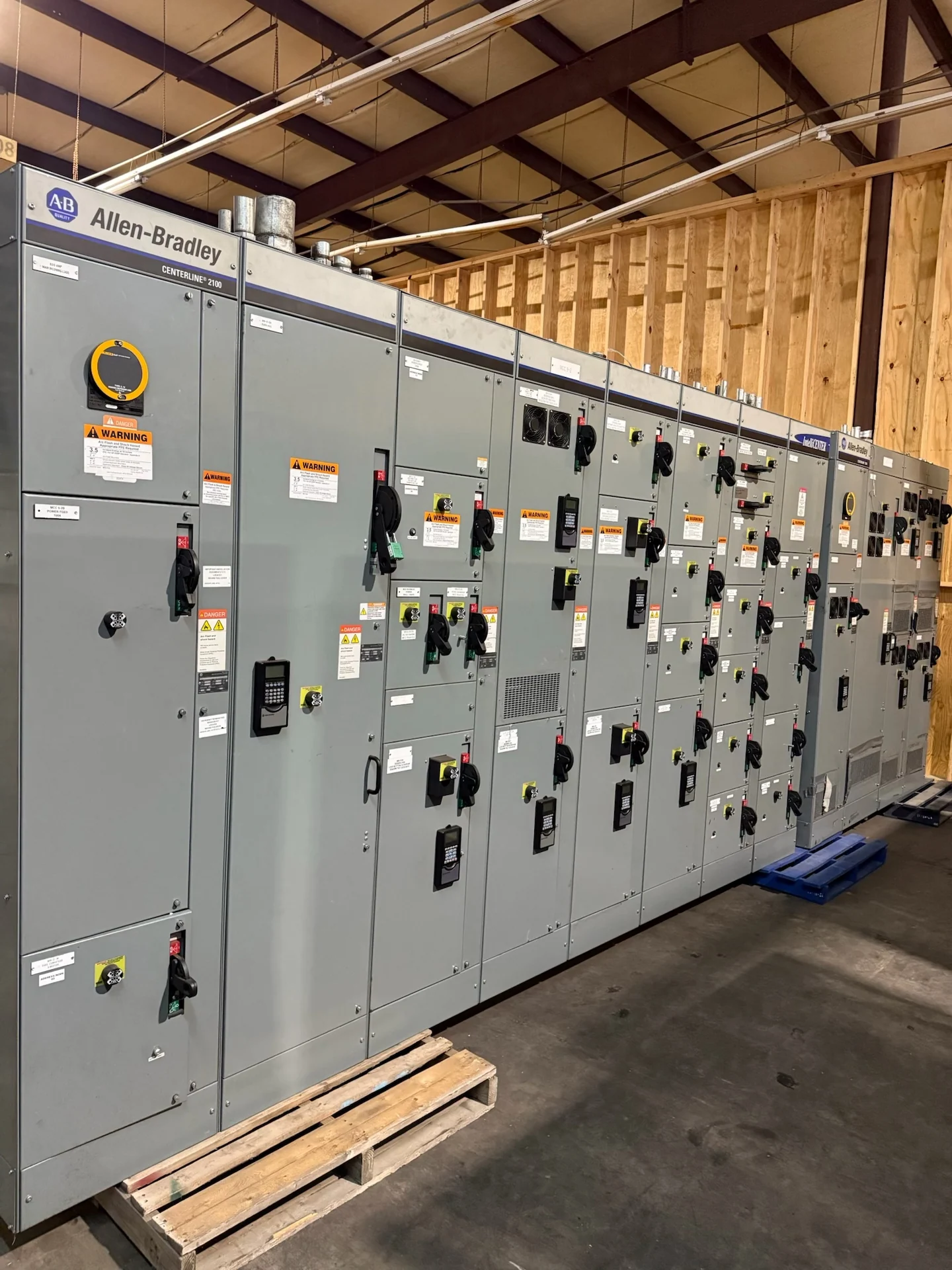
Start With the Dallas Facility Load Profile
An industrial motor control center for a Dallas, Texas project should begin with the loads it must serve, not with a preferred enclosure arrangement. List pumps, conveyors, fans, compressors, mixers, and other process motors; record horsepower, voltage, phase, full-load current, starting method, duty cycle, and whether each load is essential. Note which motors operate together, which are intermittent, and which process functions cannot tolerate an unexpected stop. That information lets the manufacturer organize feeders, select appropriate motor protection, and develop a lineup that matches the operating sequence rather than forcing the plant to adapt to an incomplete equipment concept.
Define Starters, Drives, and Protection
Motor starters and drives solve different operating problems, so the specification should identify the intended control method for every bucket or section. Across-the-line starters may suit straightforward motors, while reduced-voltage starting or variable frequency drives may be considered where acceleration, process control, or electrical-system impact requires it. Ask the design team to define overload protection, short-circuit protection, disconnecting means, bypass needs, drive input and output details, harmonic considerations, and fault-duty information. A custom manufacturer can then coordinate the selected devices with the motor schedule and clarify which decisions remain with the engineer of record.
Coordinate the Control Interface
The control interface deserves its own review because a motor control center is part of a broader automation system. Identify whether commands and status signals will be hardwired, networked, or divided between both methods. Document start, stop, permissive, interlock, alarm, fault-reset, local-remote, and emergency-stop expectations for each motor group. Include the intended communication protocol when applicable, terminal locations, spare points, control voltage, and segregation requirements. A clear cause-and-effect description helps the manufacturer lay out terminal blocks and wiring consistently, while the controls contractor can verify that the proposed interface matches the plant control architecture before fabrication.
Plan the Dallas Installation Interface
Physical conditions in the project documents should be just as specific as the electrical ratings. Provide available room dimensions, lineup orientation, incoming and outgoing cable paths, conduit entry locations, access doors, maintenance clearances, lifting or movement constraints, and the intended mounting surface. For a Dallas installation, the project team should also identify whether equipment is indoors or outdoors and describe temperature, dust, moisture, washdown, corrosive exposure, and ventilation conditions that affect enclosure selection. These details support a practical layout and reduce conflicts between the motor control center, building structure, process equipment, and installation contractor.
Prepare a Complete Manufacturer Quote Request
A useful quote request should include the one-line diagram, motor schedule, control narratives, site conditions, available fault current, system grounding, short-circuit requirements, enclosure expectations, dimensions, metering needs, and desired project documentation. State whether the scope includes starters, drives, feeder sections, communications hardware, spare buckets, control transformers, or field-installed accessories. Customers buying new industrial motor control centers from Switchgear Builders can request a custom configuration built to specification, with American components and nationwide shipping from the manufacturer. The final scope, drawings, commercial terms, and project-specific availability should be confirmed before an order is placed.
Review Drawings, Testing, and Delivery Details
Before release, review the proposed lineup against the motor schedule, control narrative, one-line diagram, physical footprint, and installation sequence. Check device identifiers, feeder destinations, wire numbers, terminal assignments, nameplate data, spare provisions, door arrangements, and interlocks. Agree on inspection and electrical test requirements that are appropriate to the project, along with the records that will accompany the equipment. For nationwide shipping to Dallas, coordinate shipping splits, weights, lifting points, protective packaging, receiving access, and freight responsibilities. The installing team should inspect the shipment on arrival and reconcile the equipment against approved drawings before connecting power. Include a named receiving contact and confirm whether the site can accept the planned truck, crane, forklift, or rigging arrangement. If the lineup is divided into sections, mark each section clearly and keep the shipping sequence aligned with the installation plan. Electrical contractors should also identify field connections and any startup checks that require coordination with controls personnel, commissioning staff, or the facility operator.