Plan the Distribution System Around the Treatment Process
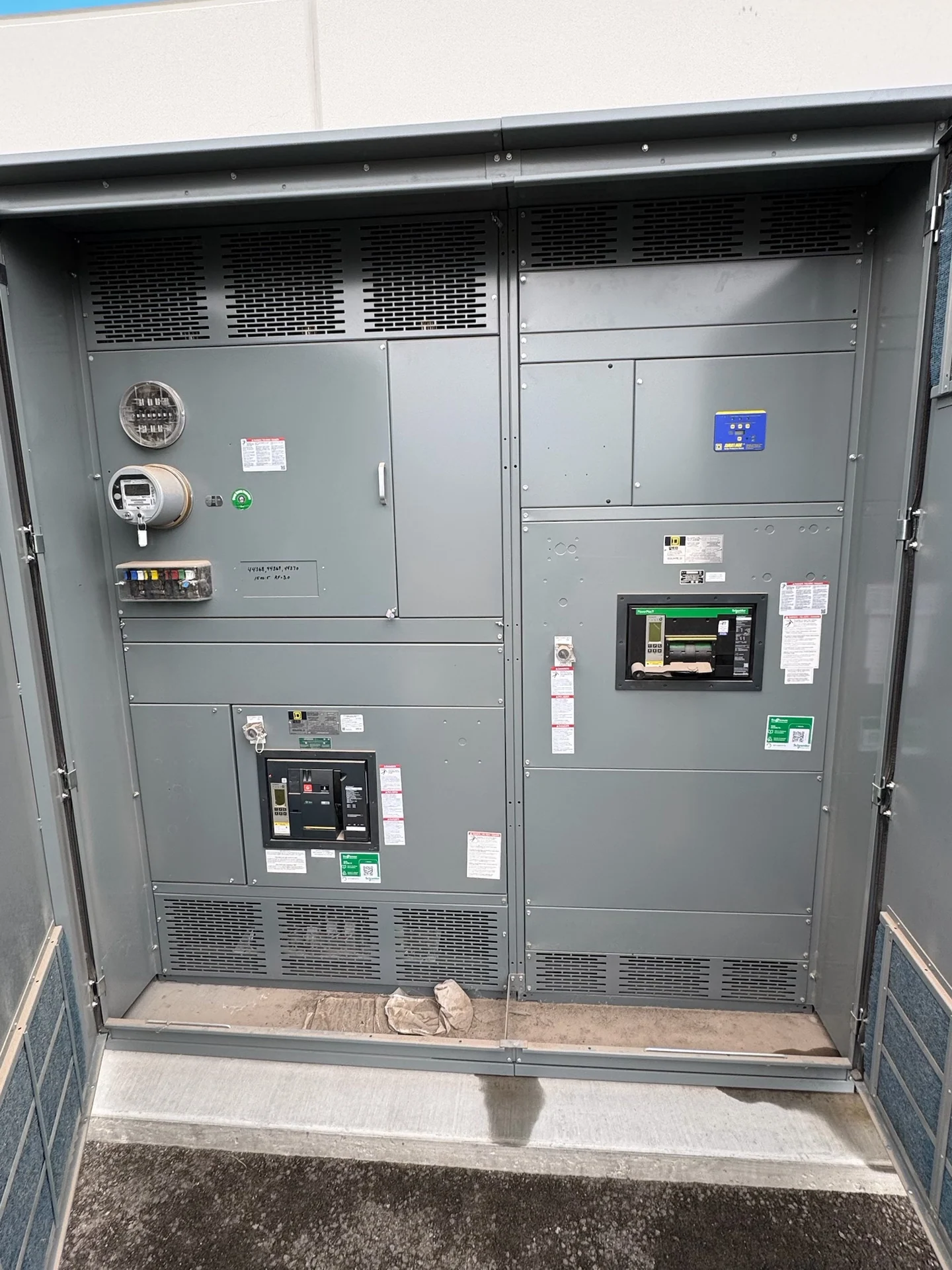
A Charleston, West Virginia water-treatment project begins with the process sequence, not a catalog label. Identify incoming sources, service voltage, available fault current, feeder lengths, pump groups, chemical systems, aeration loads, and other continuously operating or intermittently started equipment. A new motor control center can then be arranged around the one-line diagram, the facility footprint, and the operating responsibilities of the plant. Switchgear Builders manufactures custom new electrical equipment in the United States, using American components and shipping nationwide; final construction remains subject to the project drawings, engineering review, and site requirements. For a Charleston-area specification, separate raw-water intake, treatment-train, sludge-handling, and finished-water loads so a process change does not obscure feeder priorities. Ask whether the motor control center must support phased replacement while existing pumps remain energized, and identify outage boundaries before layout approval.
Match Motor Starters and Drives to Pump Duty
Pump motor selection affects starting current, process control, mechanical stress, and the electrical lineup. Across-the-line starters may suit some constant-speed duties, while a variable frequency drive may support adjustable flow or pressure where the pump, motor, controls, and process engineer allow it. Compare starting method, motor horsepower, acceleration requirements, bypass preferences, harmonic considerations, heat dissipation, and maintenance access for each load. A useful Charleston electrical distribution specification identifies which pumps are duty, standby, or sequenced, rather than treating every bucket in the motor control center as interchangeable. Pump curves and minimum-flow requirements also help distinguish a drive application from a starter application, especially when seasonal demand changes the operating range.
Account for Water-Treatment Environmental Conditions
Water and wastewater spaces can expose electrical equipment to humidity, condensation, washdown, corrosive chemicals, temperature variation, and restricted ventilation. The equipment location, enclosure selection, gasketing approach, conduit entries, space heaters or other environmental provisions, and separation from process hazards should be evaluated by qualified project personnel. Outdoor or partially enclosed installations require a different review from a conditioned electrical room. Provide the manufacturer with the site environment, elevation if relevant, room details, cleaning practices, and any project-defined enclosure or ingress requirements before the design is finalized. Chemical storage and hypochlorite areas deserve a separate review of corrosion exposure, ventilation, and equipment-room boundaries rather than being treated as ordinary wet locations.
Coordinate Controls, Interlocks, and Communications
Controls should express the plant's intended operating sequence clearly. Define local and remote commands, permissives, emergency stops, level or pressure signals, lead-lag rotation, automatic restart behavior, alarm contacts, fault indication, and loss-of-communications response. If a supervisory control system or plant network is involved, identify the interface, signal list, protocol expectations, and ownership of programming. Interlocks between pumps, valves, drives, starters, and upstream distribution equipment need a reviewed control schematic; a manufacturer can build the physical assembly to that documented sequence, but the site team must approve how the process is meant to operate. Map hardwired alarms and permissives to the plant operator’s actual response so a failed level signal does not create an unexpected pump sequence.
Prepare a Complete Custom Equipment Inquiry
For a custom switchgear or motor control center quote serving Charleston, provide the latest one-line diagram, load schedule, motor data, feeder list, control schematics, available fault current, system grounding, short-circuit requirements, dimensions, cable-entry direction, and installation constraints. Include the number of sections, starter or drive arrangement, metering, spare provisions, nameplate information, communications, documentation, inspection expectations, and shipping destination. These inputs reduce assumptions and make comparisons meaningful. They also help reconcile process drawings with electrical layouts before fabrication, when a change is easier to evaluate than after equipment interfaces have been fixed.
Coordinate Delivery and Site Integration
A water-treatment lineup must arrive in sections that the Charleston site can receive, move, set, connect, and inspect safely. Confirm shipping splits, approximate weights, lifting points, door and route dimensions, storage conditions, rigging responsibilities, and the installer’s cable and conduit plan. Nationwide shipping can be coordinated for a U.S. project, but freight terms, packaging, transit estimates, receiving procedures, and any site restrictions should be agreed for the specific order. Before energization, qualified personnel should complete installation checks, terminations, settings, control verification, and the project-defined testing and acceptance steps.