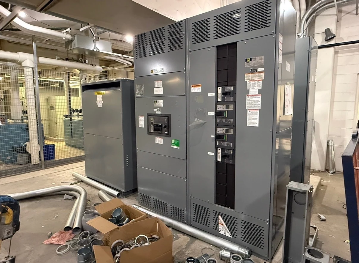
Start with the Critical-Load Operating Objective
A Charleston, West Virginia project should define which loads require source transfer, how much interruption they can tolerate, and what operating condition initiates a transfer. Critical facility loads may include life-safety systems, communications, process controls, pumps, or other functions identified by the engineer of record. Separate essential loads from convenient loads instead of placing every circuit on one transfer switch. A load schedule should identify voltage, phase, frequency, continuous current, starting characteristics, and whether a load has special sequencing needs. That information gives a manufacturer a defensible basis for configuring new automatic transfer equipment rather than guessing from a building name alone.
Define Normal and Alternate Source Capacity
Automatic transfer switch selection depends on both sources, not only the connected load. Document the normal source, alternate source, grounding arrangement, available fault current, upstream protective devices, and generator or alternate-source capacity where applicable. The alternate source must support the intended load profile, including motor starting, inrush, nonlinear loads, and staged restoration. Engineers should also state whether multiple switches will start loads in a sequence or whether one switch serves a consolidated lineup. These inputs help Switchgear Builders develop custom new electrical switchgear and transfer equipment to the project requirements, using American components and coordinating the equipment package for nationwide shipment from the manufacturer.
Coordinate Transfer Sequence and Controls
The transfer sequence should be written in operational terms before a control scheme is finalized. Identify acceptable source-sensing thresholds, time delays, retransfer behavior, test modes, manual controls, and the response to an alternate source that is available but not yet stable. Open-transition and other transition arrangements have different effects on connected loads, so the engineer should select the approach for the application rather than treating transfer equipment as interchangeable. Interlocks, remote indications, alarm contacts, communications, and load-shed signals should be shown on the control narrative and wiring documentation. A clear sequence also gives installers and operators a common reference during commissioning.
Match Protection and Distribution Interfaces
Protection coordination is a central design task when an automatic transfer switch serves critical facility loads. The project team should provide one-line diagrams, breaker data, trip settings when available, conductor information, and the calculated fault duty at the equipment location. Review bypass or isolation requirements, upstream and downstream disconnects, neutral switching, grounding conductors, and selective coordination objectives as applicable to the system. The transfer equipment enclosure, terminals, cable-entry direction, and maintenance clearances must also fit the electrical room and installation path. Switchgear Builders can use these documented interfaces to prepare a custom manufacturer package; final settings and field installation remain subject to qualified engineering review.
Plan Maintenance Access and Project Documentation
Critical-load transfer equipment should be planned for inspection, testing, and service without overlooking the people and space needed to perform that work. Confirm working clearances, door swing, cable access, lifting or movement constraints, isolation procedures, and the intended location of control interfaces. A useful submittal package may include an equipment layout, one-line diagram, elementary or wiring diagrams, terminal schedules, device information, operating sequence, and project-defined test documentation. If the project references UL 891 or another standard, confirm its applicability and any required listing or verification for the specific equipment and configuration.
Prepare a Charleston Project Inquiry
For a manufacturer quote request, identify the Charleston, West Virginia destination, project phase, equipment location, source voltages, system frequency, phase and wire arrangement, load schedule, fault information, enclosure environment, dimensions, cable-entry preferences, control sequence, documentation expectations, and shipping access. Include available drawings and explain whether the equipment is for a new installation, an expansion, or a planned replacement so interfaces can be evaluated accurately. Buying new switchgear directly from an American manufacturer is most productive when the inquiry distinguishes required facts from open design questions. Switchgear Builders manufactures custom new electrical switchgear to specification, incorporates American components, and supports nationwide shipping coordination for the defined project scope.