What Electrical Busway Does in a Distribution System
Electrical busway is an enclosed distribution assembly that carries power between a source of electrical distribution equipment and connected loads. Instead of routing many individual conductors through a long pathway, a busway system uses supported bus conductors, an enclosure, joints, and connection points selected for the application. The practical choice depends on current, voltage, phase and wire configuration, fault duty, installation environment, and the physical path. A useful electrical busway selection therefore begins with the one-line diagram and load schedule, not with a nominal product name. Switchgear Builders manufactures new custom electrical equipment in the United States, using American components and shipping nationwide; the final busway interface remains subject to project engineering and specified requirements.
Start With the Electrical Interface
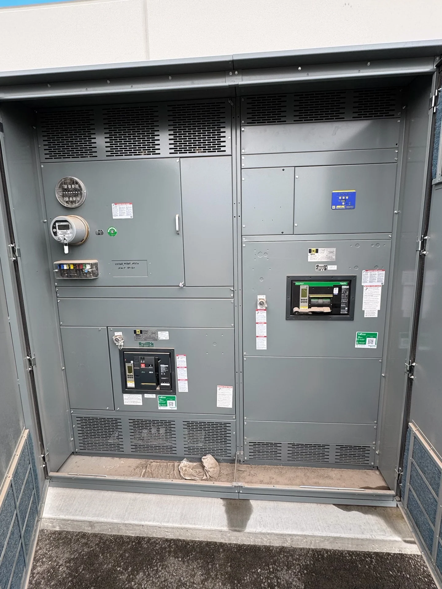
Before a busway layout is developed, define exactly where it connects to upstream and downstream equipment. The design team should identify the source lineup, feeder or transformer connection, load equipment, grounding method, system frequency, nominal voltage, continuous current, available fault current, and required protective devices. Confirm whether the connection is intended for a switchgear section, switchboard, transformer, motor control center, panelboard, or another assembly, because each interface can impose different space, termination, and access needs. Connection orientation, phase sequence, neutral requirements, and equipment bus arrangement should appear in coordinated drawings so that a custom manufacturer-built assembly matches the electrical design rather than relying on assumptions.
Routing, Space, and Support Planning
Routing is both an electrical and constructability decision. Map the busway path around columns, walls, fire-rated boundaries, doors, structural members, piping, ventilation, and required working space. Record straight lengths, offsets, elbows, elevation changes, penetration points, and termination elevations, then compare those dimensions with the installation path from receiving to the final location. Supports and anchorage must be coordinated with the building structure and the busway manufacturer's installation requirements; they should not be improvised from a drawing that shows only a centerline. Provide access for joint assembly, inspection, maintenance, and future tap-off work while preserving the clearances required by the project and applicable regulations.
Joint Coordination and Connection Details
Every joint is a coordination point where electrical continuity, mechanical alignment, enclosure integrity, and installation sequence meet. A project package should identify joint locations, joint hardware, torque and inspection requirements, phase orientation, neutral and ground continuity, and any joint covers or barriers required by the selected system. Coordinate busway joints with equipment flanges, termination boxes, cable entries, and expansion or building movement considerations where applicable. The installer also needs a clear sequence for setting sections, aligning housings, completing joints, and connecting equipment. Manufacturer review of dimensions and interfaces before fabrication can prevent a field conflict that would otherwise affect access or require unplanned modification.
Choosing Feeder and Plug-In Arrangements
Feeder busway is commonly planned as a defined path between distribution points, while plug-in busway can support distributed connection points when the system and project allow that arrangement. The choice should reflect load locations, future changes, tap-off protection, enclosure exposure, personnel access, and the ability to isolate equipment for work. Do not treat plug-in openings as a substitute for a coordinated protection design: each connected load still requires an appropriate protective device and connection method. Review loading diversity, expected expansion, conductor material, temperature and environmental conditions, and the physical service space around tap boxes. A custom quote should state which sections, joints, connection boxes, devices, supports, and drawings are included.
Documentation, Review, and Delivery
A complete busway package should make field installation and review measurable. Useful documents may include a route plan, dimensioned elevations, joint schedule, connection details, equipment interface drawings, bill of material, installation instructions, and project-defined inspection or electrical test records. Before release, compare the busway route with the latest architectural, structural, mechanical, and electrical drawings, and resolve responsibility for supports, penetrations, firestopping, rigging, field terminations, and receiving inspection. For a manufacturer quote, provide the one-line diagram, load data, equipment dimensions, route dimensions, site conditions, destination, and requested documentation. Shipping sections must be protected and identified so the receiving team can verify the shipment against the approved layout without assuming current availability or a delivery date.