Start with the Distribution Path
Busway vs. cable for power distribution is not a universal winner-versus-loser decision. The better choice follows the route, load pattern, installation method, and future changes expected in the facility. Busway packages conductors in a purpose-designed housing with connection points along a defined path, while cable systems use individual conductors or multiconductor assemblies routed through tray, conduit, or another approved support system. A useful comparison begins with the one-line diagram, source and load locations, continuous current, available fault current, voltage, phase, grounding method, ambient conditions, and the physical path between equipment. Those inputs also determine how a custom switchgear lineup must interface with the distribution system.
Routing and Space Coordination
Routing often separates the two approaches in practical terms. Busway can create a compact, recognizable path where straight sections, elbows, flanges, and tap points are coordinated as a system. Cable may better suit irregular routes, congested spaces, long transitions, or installations where support infrastructure is already defined. Compare bend radii, elevation changes, penetrations, equipment-room clearances, fire and environmental requirements, access for installation, and the route needed for future work. Confirm how the distribution path enters or leaves switchgear, transformers, panelboards, and motor-control equipment; the physical interface should be drawn, dimensioned, and reviewed before fabrication rather than assumed from a generic symbol.
Capacity, Fault Duty, and Electrical Selection
Capacity is more than selecting a current number. The design team should compare calculated demand, continuous loading, diversity assumptions, ambient temperature, voltage drop, conductor arrangement, and expected load growth. For busway, review the specified system rating, joint arrangement, tap-off provisions, and compatibility with upstream and downstream protective devices. For cable, review conductor material and size, insulation, parallel runs, ampacity adjustment, termination space, and routing effects. In either case, the assembly and connected protective equipment must be evaluated against available fault current and the applicable short-circuit requirements. A manufacturer can build new switchgear to the documented interface, but the engineer of record must establish system values and coordination criteria.
Installation Interfaces and Project Labor
Installation planning should account for more than material quantity. Busway sections require accurate field dimensions, alignment, supports, joint access, and a sequence that allows sections to be brought into position and connected. Cable systems require pulling paths, reel handling, pulling tension controls, bend-radius discipline, supports, terminations, and space for testing. Compare the work available during the outage or construction window, the route's access restrictions, lifting and handling needs, and who owns each field measurement. Shop drawings should identify connection points, section lengths, cable entry details, and equipment elevations so installers can coordinate interfaces before the shipment reaches the site.
Flexibility, Expansion, and Maintenance
Flexibility depends on what may change after commissioning. A busway route with planned tap points can support orderly additions or relocations when the system and protection scheme are designed for them, while cable may offer more freedom to follow a changing or highly irregular route. That apparent flexibility has trade-offs: every future modification still requires load calculations, protection review, safe isolation, access planning, and documentation updates. Evaluate inspection access, joint or termination maintenance, replacement procedures, spare capacity, and the consequences of a fault in a congested area. Choose the arrangement that makes the intended operating and maintenance tasks understandable and achievable for qualified personnel.
Coordinate the Switchgear Package
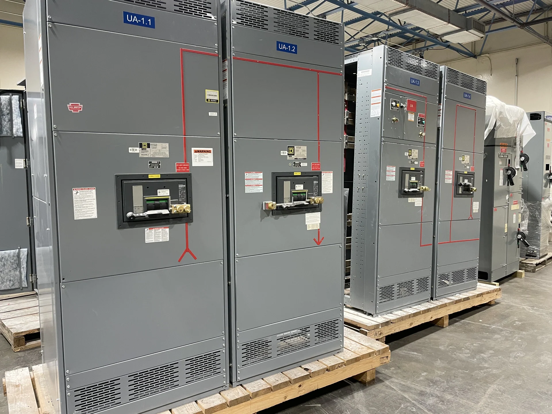
A sound electrical distribution planning package makes the busway-or-cable decision traceable. Provide the manufacturer with the latest one-line diagram, equipment schedules, elevations, connection dimensions, conductor information, protection requirements, environmental conditions, shipping constraints, and required drawings or test records. Switchgear Builders manufactures new custom switchgear in the United States, using American components and offering nationwide shipping; the exact build, component selection, documentation, and shipping arrangement remain subject to project review. Ask for a quote that clearly identifies included interfaces, assumptions, exclusions, approval steps, and information still required. Confirm any applicable standard, including whether UL 891 applies to the specific assembly and what project-specific verification is required.