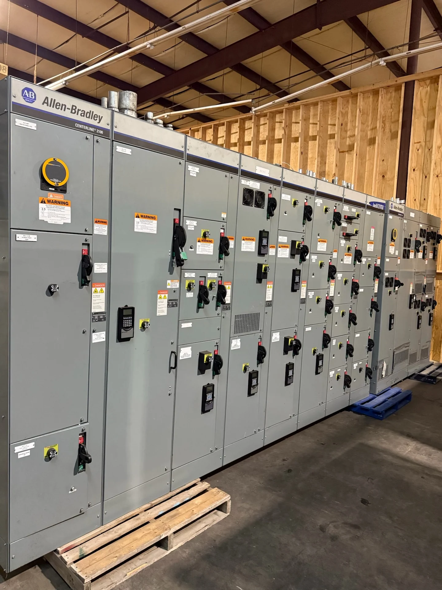
What Fixed-Mounted Low-Voltage Switchgear Means
Fixed-mounted low-voltage switchgear places protective devices in a permanent equipment position rather than on a removable drawout carriage. That arrangement can suit a distribution lineup when the project values a defined footprint, straightforward conductor routing, and a stable device layout. Selection begins with the electrical one-line diagram, nominal system voltage, phase and wire configuration, continuous current, available fault current, and the protective functions required for each main or feeder. A manufacturer can build new equipment custom to those documented requirements, with the final device arrangement and applicable construction requirements confirmed during engineering review.
Start With Electrical and System Inputs
A useful fixed-mounted low-voltage switchgear selection records more than a bus ampere value. Provide the calculated loads, future capacity expectations, source and feeder information, grounding method, frequency, short-circuit data, conductor sizes, termination preferences, and any metering or control interfaces. Protective-device interrupting ratings must be evaluated against available fault current, while continuous ratings and temperature assumptions should align with the project design. If the lineup includes a main, tie, or multiple sources, describe the intended operating sequence and interlocking logic before a quote is finalized.
Space, Access, and Internal Arrangement
Fixed construction can make the lineup layout predictable, but it does not remove the need to plan access carefully. For example, a feeder device may need front access for settings review while its line and load conductors enter from opposite sides; that geometry affects enclosure depth, lug orientation, and the order of field terminations. Record whether cables, busway, or conduit approach from above or below, and identify minimum bending radii from the selected conductors. A floor plan should also show adjacent equipment, doors, columns, and temporary laydown space. These details help distinguish a genuinely compact arrangement from one that merely has a small nameplate footprint but becomes difficult to wire, test, or service after installation. Coordinate enclosure dimensions, door swing, cable entry, bend space, working clearances, ventilation, lifting provisions, and the path from receiving to the electrical room. Device handles, trip units, fuses where applicable, terminals, control wiring, and inspection points should remain reachable for qualified personnel without relying on a removed device. A custom builder can review the room drawing and installation interfaces so the proposed electrical distribution equipment fits both the one-line and the physical site constraints. Confirm the isolation procedure and the clearance needed to remove a fixed device or its connections.
Fixed-Mounted Versus Removable Arrangements
The central trade-off is maintenance and replacement method. A fixed-mounted protective device generally requires planned isolation and work at the enclosure when the device must be serviced or changed, whereas a removable arrangement can be designed around withdrawal space and a different maintenance procedure. Fixed construction may reduce carriage-related space and simplify a compact lineup, but the owner should consider outage planning, spare-device strategy, torque and connection inspection, and the skills and procedures available to the operating team. The right choice depends on the risk assessment, access rules, lifecycle plan, and engineer-approved sequence rather than on a generic preference.
Planning a New Replacement Lineup
When a new fixed-mounted lineup will replace existing distribution equipment, collect the available one-line, elevations, wiring diagrams, protective-device data, nameplate information, feeder schedules, room measurements, and photographs of connection points. Confirm which interfaces must remain aligned, including incoming conductors, outgoing feeder locations, control power, metering, grounding, and communication wiring. Also document outage boundaries, demolition and installation responsibilities, rigging constraints, and commissioning checks. The manufacturer can use those inputs to develop a custom proposal, while a qualified design team confirms compatibility, protection coordination, field safety procedures, and the final installation plan.
Build, Documentation, and Nationwide Delivery
Switchgear Builders manufactures new electrical switchgear in the United States, builds custom equipment to specification, uses American components, and ships nationwide. For a fixed-mounted project, request a scope that identifies enclosure construction, bus and device arrangement, control wiring, metering, drawings, inspection points, test documentation, packaging, and shipping responsibilities without assuming an inclusion. Confirm the project-specific standards, any required testing or witness steps, and whether UL 891 applies to the particular assembly; applicability and any listing must be confirmed for that project.