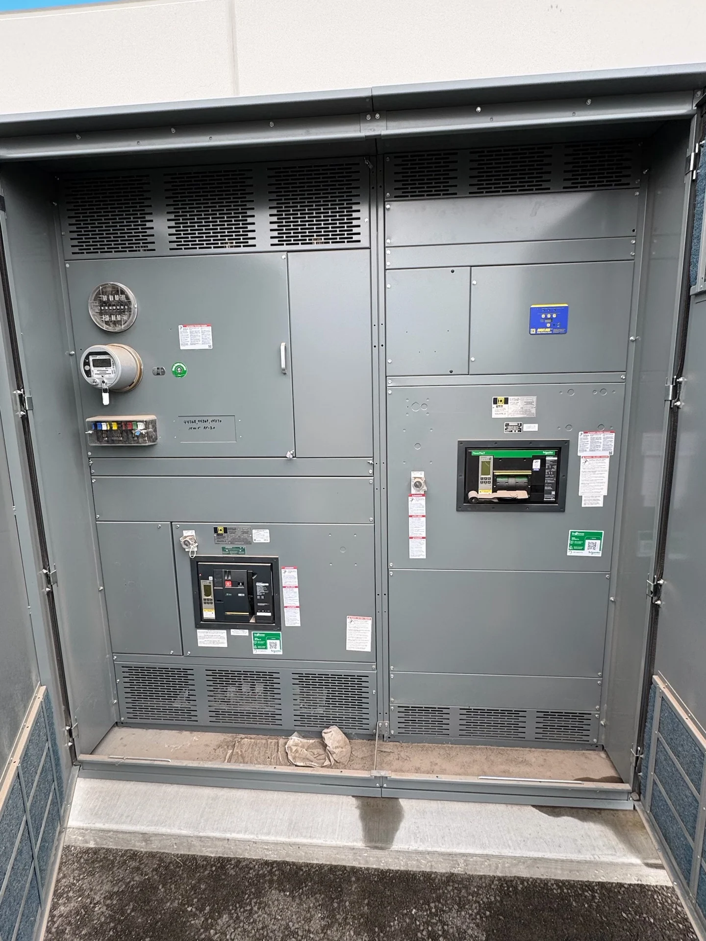
What Low-Voltage Switchgear Does
Low-voltage switchgear is a coordinated assembly for controlling, protecting, and distributing electrical power on the load side of a low-voltage source. A lineup can bring a main device, bus conductors, feeder breakers, metering, control wiring, and connection compartments into one planned arrangement. The correct solution depends on the system voltage, phase and wire configuration, continuous load, available fault current, grounding method, and operating sequence. Built to project specifications, new electrical switchgear from Switchgear Builders is manufactured in the United States with American components and shipped nationwide. Each design still requires project-specific engineering review before fabrication.
Start With Electrical Ratings
A useful low-voltage switchgear selection begins with electrical data rather than enclosure size. The equipment specification should identify nominal system voltage, frequency, phase arrangement, service or feeder application, required continuous current, and the available short-circuit current at the installation point. Main and feeder protective devices must have ratings appropriate to the calculated duty, while the assembly bus and supporting structure must be specified for the project's applicable short-circuit requirement. Load calculations, transformer information, utility data, grounding details, and coordination studies give the manufacturer a sound basis for developing a custom lineup.
Choosing Breakers and Protective Functions
Breaker selection affects interruption, maintenance, adjustment, connection method, and the physical organization of the lineup. The design team may evaluate fixed or drawout arrangements, main and feeder frame sizes, trip functions, accessory contacts, shunt or undervoltage releases, and communications requirements when those functions are part of the project. Protection settings should be coordinated with upstream and downstream devices by the responsible electrical engineer; a breaker’s catalog rating alone does not establish system coordination. Identify required poles, neutral treatment, ground-fault functions, control voltage, and interlocking logic before requesting a quote.
Plan the Lineup Configuration
Lineup configuration translates the one-line diagram into a buildable arrangement. Review the number and order of sections, main-tie-main or other source relationships, bus segmentation, feeder locations, cable entry, neutral and ground bus positions, metering compartments, and spare space. Room dimensions, working clearances, door swing, removal paths, overhead obstructions, and wall or floor interfaces can change the practical layout. Drawings should show section widths, elevations, termination areas, and lifting or handling provisions so the engineer, installer, and manufacturer can resolve physical conflicts before release.
Account for the Installation Environment
Indoor and outdoor applications introduce different design questions even when the electrical ratings are similar. Confirm enclosure requirements, ambient conditions, exposure to moisture or dust, ventilation, access control, corrosion concerns, elevation, seismic inputs where applicable, and the available maintenance space. An outdoor installation may also require site coordination for foundation dimensions, conduit approaches, drainage, and weather-protection details. These conditions should appear in the project specification instead of being inferred from a product name. The selected enclosure and construction must be reviewed against the actual location and applicable project requirements.
Define Drawings, Tests, and Documentation
Before a new lineup is released, establish which documents and checks are required for acceptance. Typical project discussions cover the approved one-line diagram, elevation and dimensional drawings, schematic and wiring diagrams, device data, terminal schedules, nameplate information, and installation or maintenance material. Inspection points may include workmanship, conductor identification, clearances, torque records, continuity, insulation checks, and functional operation, with acceptance criteria agreed for the project. If UL 891 is specified, confirm its applicability, construction requirements, and any project-specific listing or verification rather than assuming it applies to every assembly.
Prepare a Manufacturer Quote Request
For a focused quote on new low-voltage switchgear, send the manufacturer the latest one-line diagram, load schedule, system ratings, fault-current information, equipment location, dimensions or room drawings, breaker schedule, control sequence, metering needs, cable details, documentation requirements, and destination. State whether the request is for a new installation, expansion, or replacement interface, and identify the parties responsible for engineering approval, installation, testing, and rigging. Switchgear Builders can review a custom scope for American components and ship nationwide; project-specific availability, pricing, and delivery details must be confirmed in the quotation.