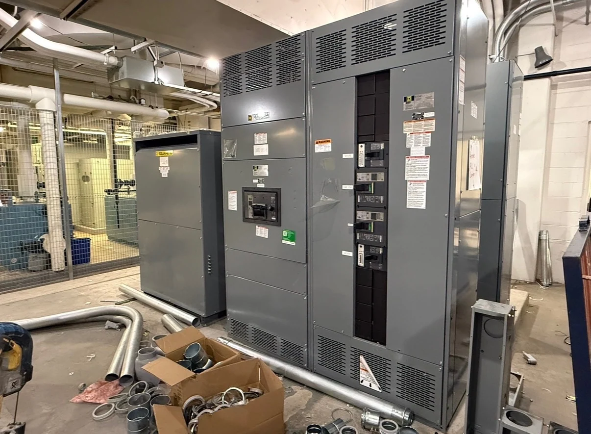
What Load-Interrupter Switchgear Does
Medium-voltage load-interrupter switchgear provides a controlled way to open and close energized feeder circuits within the switching duty defined for the project. The switch handles load current, while associated fuses, relays, breakers, or upstream devices address fault protection according to the electrical design. That distinction matters: a load-interrupter switch is not automatically a substitute for every type of overcurrent device. A useful specification identifies the nominal system voltage, frequency, phase arrangement, grounding method, continuous current, short-circuit duty, and feeder operating sequence before a manufacturer develops the lineup. Switchgear Builders manufactures new equipment in the United States, custom to project requirements, with American components and nationwide shipping.
Start with Feeder and System Data
Medium-voltage load-interrupter switchgear selection begins with the feeder context rather than a catalog label alone. Provide the source arrangement, transformer or load served, normal and alternate paths, available fault current, conductor type and termination details, elevation or environmental conditions, and whether the equipment will be installed indoors or outdoors. Engineers should also identify grounding, insulation coordination, cable shielding, phase spacing, and any utility or owner standards that govern the interface. These inputs help distinguish a simple switching position from a lineup requiring fuses, grounding switches, metering, relaying, interlocks, or sectionalizing functions. The final ratings and construction remain subject to project engineering review.
Coordinate Switching with Protection
Protection coordination determines how the load-interrupter switchgear behaves during normal operation and abnormal conditions. Time-current curves, fuse characteristics, relay settings, transformer damage limits, feeder conductor capabilities, and downstream equipment ratings should be reviewed together by the responsible electrical engineer. A switch may interrupt ordinary load current while a separate protective device clears fault current; the arrangement must be selected so the devices work in the intended sequence without creating an avoidable outage across healthy feeders. Ask for the one-line diagram, coordination study inputs, and required trip or alarm logic when requesting a quote. Do not infer interrupting capability from the switch name alone.
Define Layout, Access, and Controls
The physical design affects installation, operation, and future maintenance planning. A quote request should state lineup orientation, section dimensions or available room envelope, cable entry direction, termination space, bus arrangement, access sides, lifting or handling constraints, and the location of control and indication devices. Specify whether the operating sequence includes mechanical or electrical interlocking, key interlocks, remote status contacts, voltage indication, ground-switch provisions, metering, or communications. Indoor and outdoor applications can impose different enclosure, environmental, ventilation, and access requirements. Switchgear Builders can use these project details to develop a custom new assembly, while the engineer and installer confirm clearances, anchorage, interfaces, and field responsibilities.
Prepare a Useful Manufacturer Quote Request
A complete request for medium-voltage load-interrupter switchgear reduces ambiguity during technical review. Include the latest one-line diagram, equipment schedule, feeder and cable information, fault-current study or available fault data, control schematic requirements, physical dimensions, site conditions, shipping destination, and requested drawings or test records. Identify which items are mandatory and which are design alternatives, such as fused versus relay-coordinated protection or local versus remote operation. Ask the manufacturer to identify assumptions, exclusions, required approvals, and project-specific testing in the quotation. Comparing proposals is meaningful only when each supplier receives the same electrical, mechanical, documentation, and delivery scope.
Plan Delivery and Project Verification
Nationwide shipping requires coordination beyond the equipment drawing. Confirm the destination, receiving hours, unloading method, site access, shipment sections, estimated weights, lifting points, freight responsibilities, and protection of bushings, doors, controls, and terminations during transit. Before release, review approved drawings against the one-line diagram, cable schedule, control sequence, dimensions, and connection interfaces. If UL 891 or another standard is specified, its applicability, construction requirements, and any project-specific listing or verification must be confirmed for the exact assembly; it should not be assumed from the product category. Acceptance checks, documentation, and field installation activities should be assigned clearly among the manufacturer, engineer, and qualified installer.