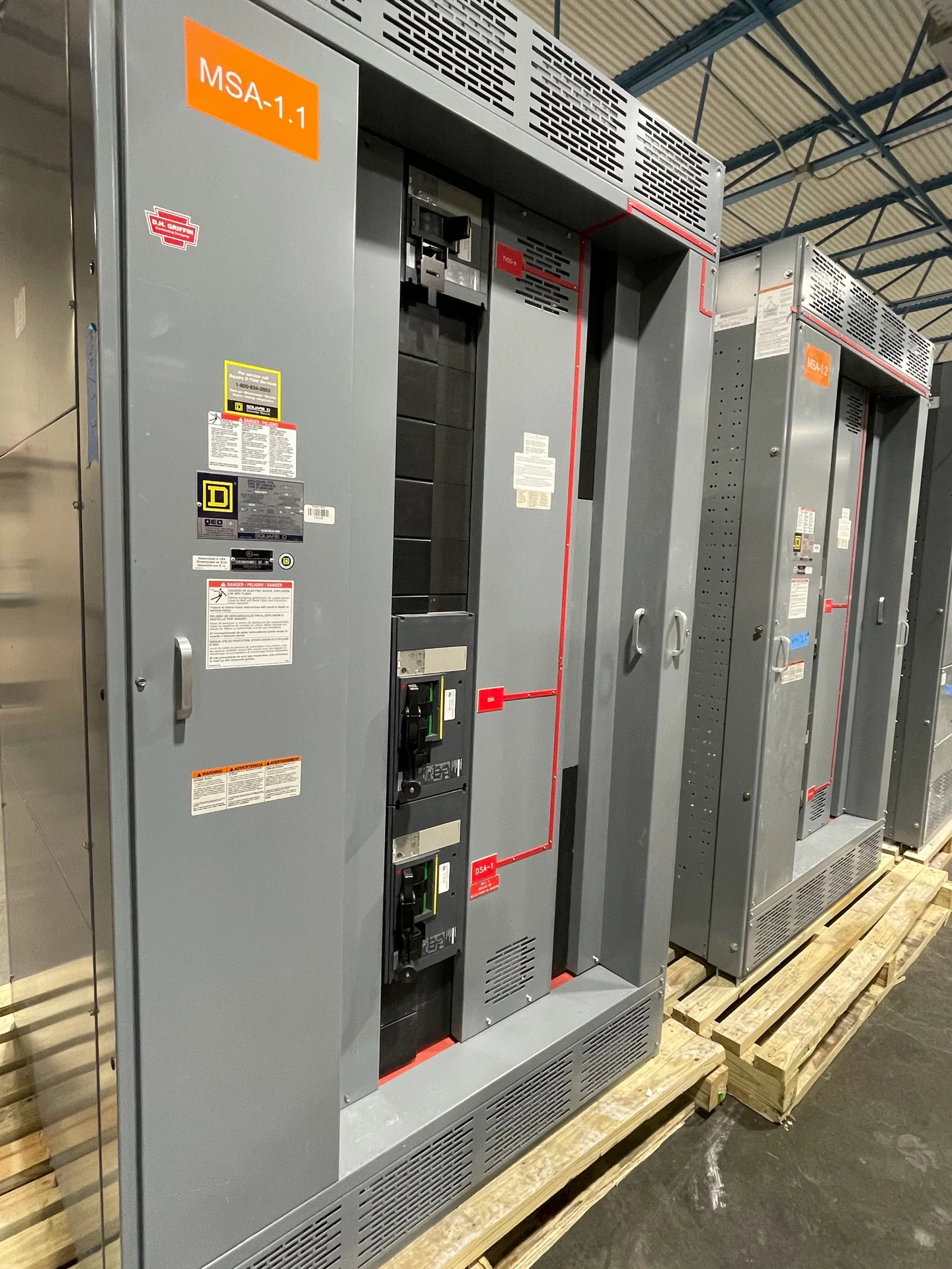
Start with the Transformer Feeder Duty
Medium-voltage switchgear for transformer feeders should be selected from the complete electrical duty, not from voltage alone. The design review begins with the source arrangement, nominal system voltage, frequency, phase configuration, grounding method, transformer primary data, continuous load, and available fault current at the equipment location. Transformer size and impedance affect fault-current calculations, while energization can create inrush that must be distinguished from a sustained fault. A manufacturer can build new equipment to the approved project requirements, using American components and coordinating a custom configuration for nationwide shipment.
Coordinate Switching and Protection
The feeder switching device and its protective functions need to work with the transformer and the upstream and downstream system. Engineers may evaluate fuses, circuit breakers, relaying, current transformers, ground-fault functions, and control power according to the equipment arrangement and study results. Time-current coordination should account for transformer damage limits, secondary protection, motor or process loads connected beyond the transformer, and the utility or source protection scheme. Settings are not chosen from a generic table; the final selection depends on the one-line diagram, fault study, operating sequence, and authority having jurisdiction requirements.
Specify the Medium-Voltage Construction
A useful medium-voltage switchgear specification describes more than a feeder ampere value. It should identify the equipment voltage class, insulation requirements, short-circuit duty, bus material and arrangement, grounding provisions, cable entrance direction, termination space, phase spacing, and access expectations. The enclosure location also matters: indoor and outdoor installations can impose different requirements for weather exposure, ventilation, drainage, corrosion, security, and maintenance access. If a metal-clad or metal-enclosed arrangement is being considered, the project team should define the intended construction and operating method rather than treating those terms as interchangeable.
Match the Feeder Interface to the Transformer
The physical connection between switchgear and transformer deserves the same attention as the protective device. Confirm whether the feeder uses shielded medium-voltage cable, bus connection, elbows, stress-control terminations, or another project-defined interface. Record cable quantity, conductor size, bending space, phase sequence, grounding conductor routing, and entry orientation before layout approval. Transformer primary terminals, neutral or grounding connections, tap arrangements, and enclosure clearances can influence the lineup dimensions. Early coordination with the transformer supplier, electrical engineer, and installing contractor reduces field changes without assuming that a standard footprint will fit every site.
Plan Controls, Interlocks, and Operations
Operating details should be written as an understandable sequence before controls are finalized. Define who may open or close the feeder, how grounding equipment is applied, what source conditions permit energization, and which doors, shutters, disconnects, or breakers require interlocking. Remote indication, local control, trip circuits, alarm contacts, metering, and communications may be included when they are part of the approved design. A custom builder needs the control schematic, terminal schedule, device list, and any required interface points, while the project team remains responsible for confirming that the sequence matches field procedures and safety planning.
Review Testing, Documentation, and Standards
Before fabrication, agree on the drawing package, inspection points, electrical checks, functional demonstrations, and records expected for the new assembly. Documentation may include an approved one-line diagram, elementary and wiring diagrams, enclosure layouts, nameplate information, device data, connection details, and test results defined by the project. Applicable standards and specifications must be identified by the engineer and purchaser; UL 891 applicability, any requested listing, and the evidence required for this medium-voltage application must be confirmed for the specific project rather than presumed.
Prepare a Complete Manufacturer Quote Request
For a productive medium-voltage switchgear for transformer feeders selection inquiry, send the one-line diagram, transformer schedule, system voltage and grounding information, available fault current, protection study inputs, indoor or outdoor location, cable and termination details, desired lineup arrangement, control voltage, metering needs, drawings, testing expectations, destination, and site access constraints. Identify whether the request is for a new installation, expansion, or replacement interface, and explain the required shipping split or lifting restrictions if known. Switchgear Builders manufactures new custom electrical switchgear in the United States and can review the equipment scope, American component requirements, documentation, and nationwide shipping arrangements. Pricing and delivery expectations depend on the project quotation.