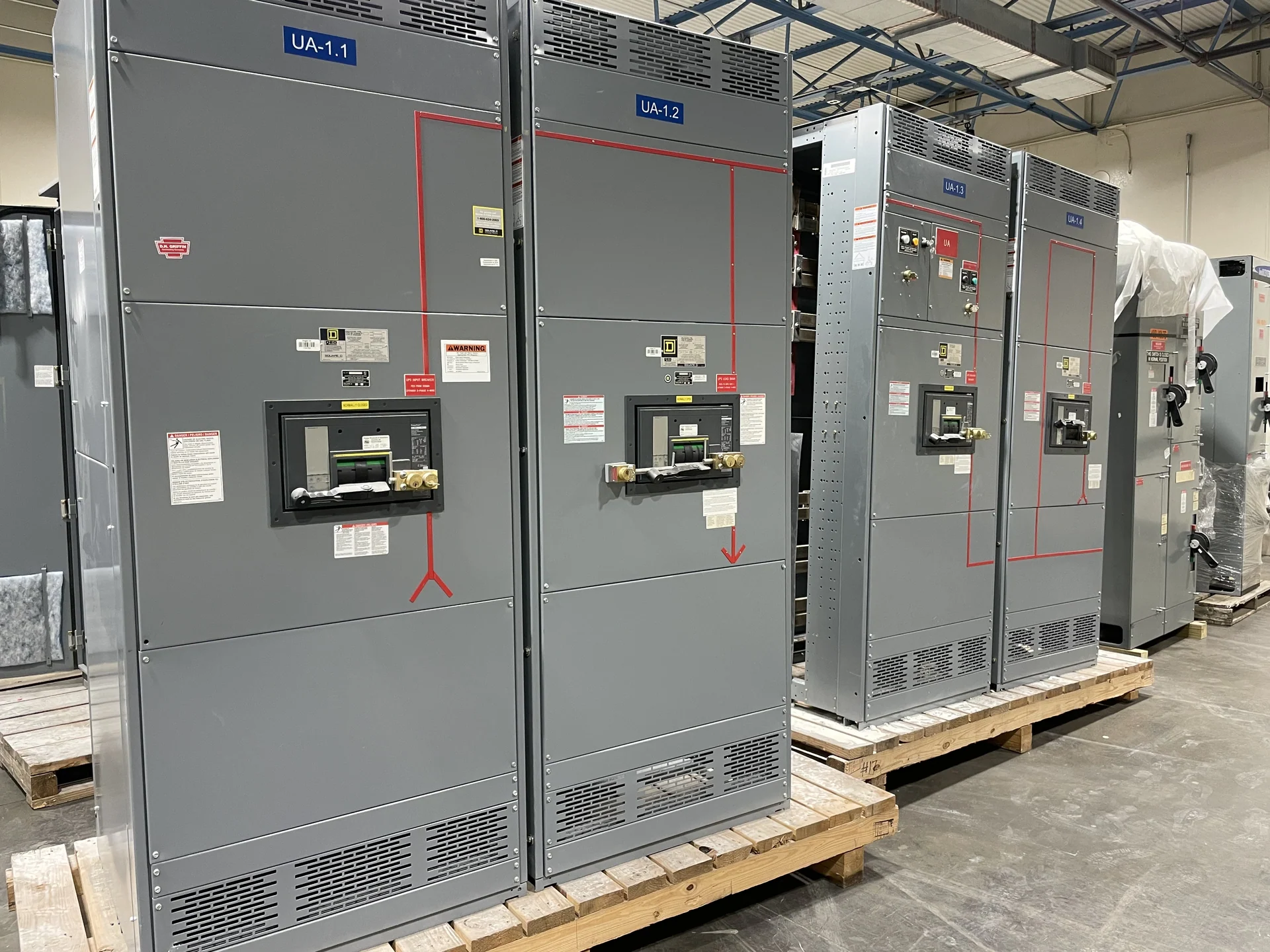
What Drawout Metal-Clad Switchgear Does
Drawout metal-clad switchgear places switching and protection devices in dedicated compartments within a coordinated lineup, allowing a qualified operator to move a removable breaker between defined positions. That arrangement separates the device from the energized bus when withdrawn and supports orderly inspection, testing, or replacement planning. A useful design begins with the distribution one-line, source arrangement, feeder duties, voltage class, continuous current, fault duty, grounding method, and the operating sequence expected by the facility. It also distinguishes the device compartment from the surrounding bus and cable compartments, which helps establish inspection boundaries and installation responsibilities.
Specify the Electrical Duty Before the Cabinet
Drawout metal-clad switchgear selection should follow the electrical duty rather than start with a preferred enclosure size. Engineers should establish nominal system voltage, frequency, phase arrangement, available fault current, interrupting requirements, bus continuous current, short-circuit withstand expectations, insulation coordination, and protective relay functions. Feeder loads, transformer interfaces, generator sources, and future circuits may change the lineup arrangement. A manufacturer can then translate those inputs into a new custom build with device compartments and connections coordinated to the project drawings. Confirming these values early also exposes conflicts between utility data, study assumptions, and equipment schedules before they reach fabrication.
Compartment Layout and Mechanical Interfaces
Each compartment needs more than a breaker outline. The project should define primary disconnect interfaces, shutters or barriers where applicable, secondary control connections, cable entry, grounding provisions, lifting or handling points, and the clearances required for operation and service. The physical travel path matters as well: doors, racking access, interlocks, and adjacent sections must work together without forcing a device through an unsafe or ambiguous position. Dimensioned elevation drawings and compartment schedules help the engineer, installer, and manufacturer resolve these interfaces before fabrication. Include the intended cable bending space and termination orientation, since those details can affect section depth, access panels, and the location of adjacent equipment.
Interlocks and Operating Sequence
Interlocks are part of the operating logic, not merely hardware added after the layout is complete. The specification should state which actions are permitted in connected, test, and disconnected positions, how the grounding circuit or shutters interact with device travel, and how source, tie, and feeder relationships are controlled. Where multiple sources exist, the one-line and control narrative should identify permitted switching states and any key exchange or electrical interlocking requirements. Final logic must be reviewed by the responsible electrical professionals and confirmed against the project design. A written sequence of operations, terminal schedule, and control-voltage definition gives the assembly team a practical reference for wiring review and functional checks.
Maintenance Access and Project Documentation
A drawout arrangement is valuable only when the facility plans how qualified personnel will inspect, test, and return equipment to service. Allow space for device handling, test equipment, door swing, cable access, and documented isolation procedures; also coordinate the movement path from the electrical room to the designated work area. The equipment package should identify device positions, terminal designations, wiring references, settings information supplied for the project, and inspection records. Clear documents help personnel interpret the equipment configuration during commissioning and future maintenance. The owner and installing contractor should also agree who provides handling equipment, field connections, labels, and final operating procedures before the lineup is released for construction.
Building New Equipment to the Project Scope
Switchgear Builders manufactures new electrical switchgear in the United States, builds custom equipment to specification, uses American components, and ships nationwide. For a drawout metal-clad inquiry, provide the one-line diagram, system ratings, lineup dimensions or room constraints, feeder schedule, control voltage, protection and metering requirements, cable information, environmental conditions, interlock narrative, and documentation expectations. Any UL 891 question must be evaluated for applicability to the specific project, equipment type, and requested documentation rather than assumed from the product name. A complete inquiry should identify the reviewing engineer, installation conditions, desired communication milestones, and any required submittal format so technical questions are resolved in the right sequence.