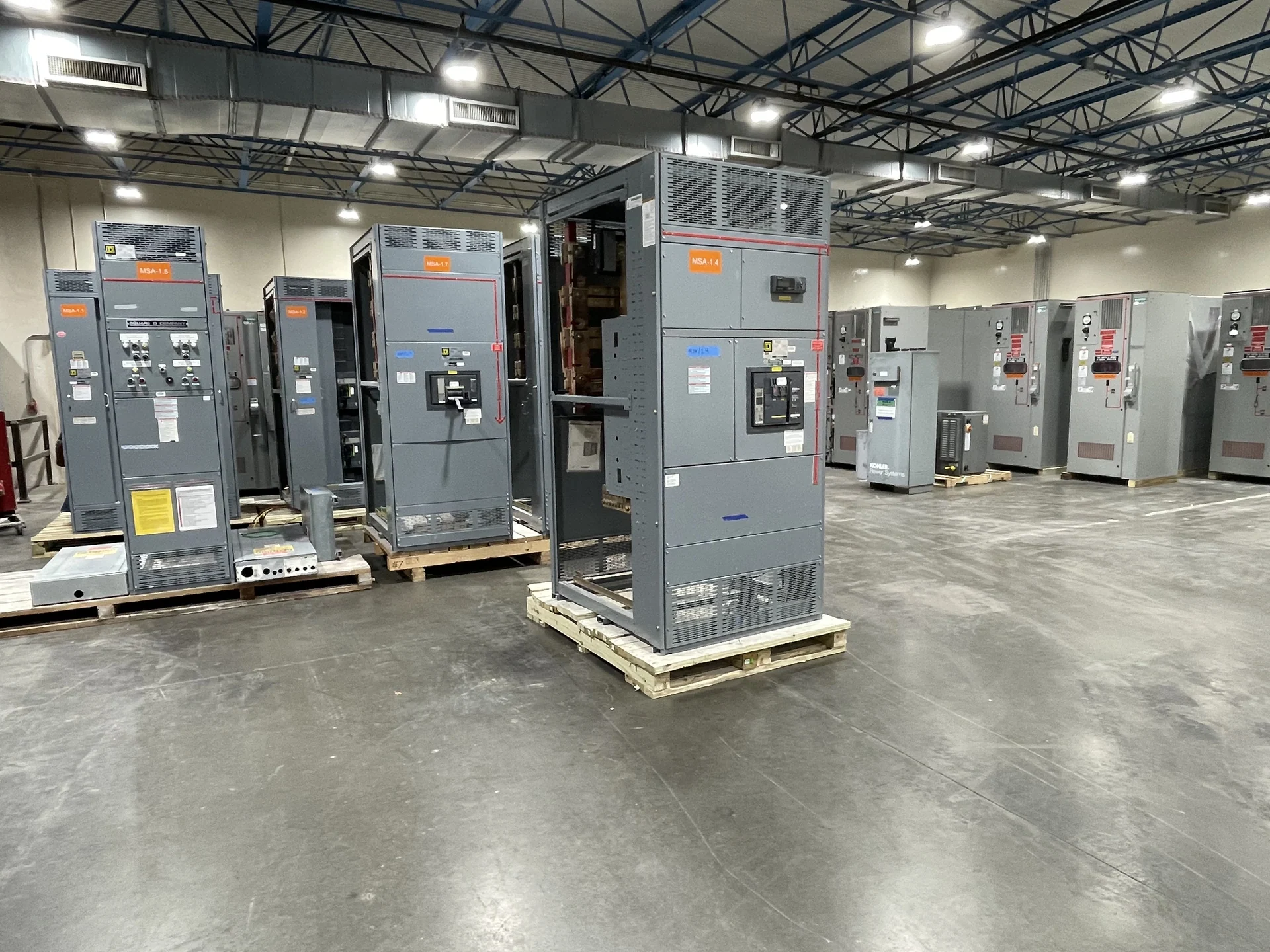
What Metal-Clad Switchgear Does
Metal-clad switchgear is an enclosed electrical distribution assembly organized around separate compartments for switching devices, bus conductors, cable connections, and control equipment. That physical separation helps define how operators access equipment, how conductors are routed, and how maintenance activities are planned. Selection starts with the system one-line diagram, nominal voltage, frequency, phase arrangement, grounding method, continuous current, available fault current, and the required switching sequence rather than with enclosure size alone. The equipment voltage class and each protective device duty should be checked against the electrical study and the intended source and feeder arrangement. A specification that omits those relationships can produce a lineup that fits physically but does not satisfy the operating plan.
Compartmentalization and Layout
Compartmentalization is a design decision with practical consequences. A project team should identify which spaces contain incoming or outgoing cables, main and feeder switching devices, bus sections, instrument transformers, relays, terminal blocks, and low-voltage controls. The layout must also account for cable bending space, access doors, shutters or barriers where applicable, ventilation, working clearances, lifting paths, and the movement route into the electrical room. Final dimensions depend on the selected devices and project drawings. Review door swing, removable panels, cable entry direction, and adjacent equipment before approval, because a convenient internal arrangement can still create an installation problem if the room access path or maintenance workspace is overlooked.
Removable Switching Devices
Removable switching devices can support a planned maintenance approach by allowing an appropriately qualified team to isolate equipment and move a device to a defined position for inspection or servicing. The specification should state the device type, continuous and interrupting duties, control voltage, racking or positioning requirements, interlocks, grounding provisions, and any keying or lockout expectations. Engineers and installers should confirm that the operating sequence, replacement access, and cable terminations work together before fabrication begins. Confirm whether the project expects drawout positions, test positions, stored-energy indications, local controls, or remote signals, and document how each status is represented at the lineup and in the control system.
Engineering Inputs for Selection
A useful metal-clad switchgear selection package includes the one-line diagram, load schedule, fault-study inputs, protection and coordination requirements, utility or service-interface information, environmental conditions, elevation when relevant, indoor or outdoor installation details, enclosure expectations, and available room dimensions. Include metering, communications, control power, interlocks, source transfer logic, and future feeder provisions when they are part of the operating plan. Those inputs allow a manufacturer to develop a custom arrangement instead of guessing at ratings or interfaces. Also identify cable sizes and entry locations, phase identification, grounding connections, terminal requirements, and the documents needed for submittal review.
Manufacturing and Documentation
Switchgear Builders manufactures new metal-clad switchgear in the United States, custom to project requirements, using American components and nationwide shipping for customer equipment deliveries. The project package should identify required drawings, bills of material, nameplate data, wiring diagrams, device manuals, inspection points, and electrical or functional checks. If UL 891 is referenced, the engineering team must confirm whether it applies to the particular assembly and separately verify any project-specific listing or documentation requirement before the order is finalized. Clear document control matters as much as physical assembly: approved revisions, device data, wiring identifiers, and test records should correspond to the equipment configuration that will be installed.
Planning Delivery and Installation
Delivery planning should address lineup sections, shipping splits, weights, lifting points, door and corridor dimensions, receiving space, storage conditions, rigging responsibility, and the sequence for setting and joining sections. Provide the destination and site constraints early so packaging and freight coordination can be evaluated for the specific project; nationwide shipping does not remove the need for a qualified receiving and installation plan. Before energization, the responsible electrical professionals should complete project-defined inspections, connections, settings, and testing. Coordinate field termination details with the installation team, including bus joining, grounding, control wiring, device insertion, alignment, and the records required to release the lineup for operation.