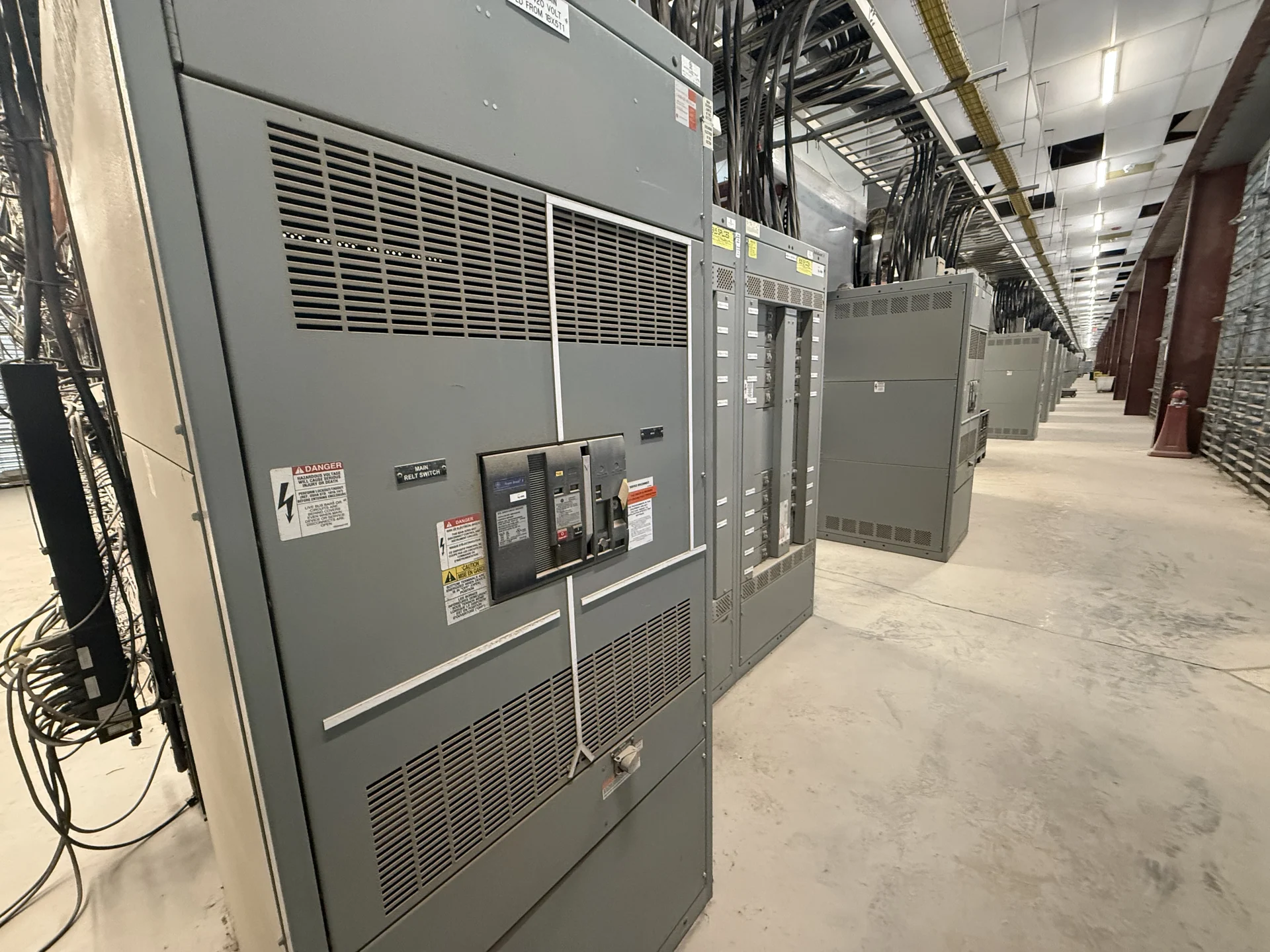
Metal-Clad Switchgear in Plain Terms
Metal-clad switchgear is a coordinated electrical distribution assembly in which switching and protective devices sit inside grounded metal compartments. The enclosure is more than a weather or touch barrier: its internal arrangement separates functional areas, guides cable and bus connections, and establishes how operators access equipment. A metal-clad lineup may include incoming sections, feeder sections, a bus compartment, instrument compartments, and spaces for removable circuit breakers. The final arrangement depends on system voltage, fault duty, operating sequence, maintenance approach, and the project drawings rather than on the name alone.
How Compartmentalization Affects the Design
Compartmentalization defines what is separated, where conductors terminate, and which components can be accessed during an operating or maintenance procedure. A project team should identify the main bus, feeder paths, cable compartments, grounding provisions, low-voltage control areas, and barriers between energized functions. These choices influence enclosure dimensions, cable bend space, door and panel access, ventilation, lifting points, and the physical route from shipping through the electrical room. Clear drawings should show section boundaries and interfaces so the manufacturer, engineer, and installer are working from the same interpretation.
Switching and Protection Choices
The devices inside a metal-clad lineup determine how the system is switched, isolated, and protected. Depending on the application, the specification may call for drawout circuit breakers, fixed switching devices, fuses, grounding switches, instrument transformers, relays, metering, or control power equipment. Device selection must match nominal system voltage, continuous current, interrupting or withstand duty, grounding method, frequency, phase arrangement, and protection philosophy. Engineers also need to define interlocks and operating sequences so a practical layout supports the intended switching procedure without assuming that every metal-clad assembly uses the same device combination.
Ratings, Clearances, and Project Verification
A useful metal-clad switchgear specification starts with calculated electrical information, not a generic product label. Provide the available fault current, source characteristics, load schedule, transformer data, voltage class, bus rating, feeder requirements, insulation coordination inputs, and grounding details when applicable. Confirm physical working clearances, room dimensions, cable entry direction, elevation, environmental exposure, seismic or anchorage criteria, and utility interfaces. Applicable standards and any requested construction or listing requirements must be reviewed for the specific project; UL 891 applicability, if raised, should be confirmed rather than assumed.
Building a Custom Metal-Clad Lineup
Switchgear Builders manufactures new electrical switchgear in the United States and can develop a custom build around the approved one-line diagram, equipment schedule, control narrative, and physical constraints. American components can be incorporated when required by the project scope, with exact component selections and origin details confirmed during engineering and procurement. A practical quote package should state section count, device arrangement, bus material, control voltage, metering, relaying, cable terminations, finish, documentation, testing expectations, and shipping destination. Nationwide shipping can be coordinated for the completed equipment, with packaging, split points, lifting provisions, and receiving responsibilities defined for the project.
Questions to Resolve Before Ordering
Before ordering new metal-clad switchgear, align the engineer, electrical contractor, owner, and manufacturer on the approved drawings and the installation plan. Ask who supplies field cable terminations, which settings are furnished for protective relays, how control power is sourced, what factory inspection records are required, and whether witness points apply. Confirm the destination, access route, unloading method, storage conditions, and site readiness without relying on an assumed schedule. A complete inquiry lets the manufacturer identify missing technical inputs early and keeps the final lineup tied to the actual distribution system. Include the latest approved drawing revision, identify every incoming and outgoing termination, and distinguish factory-installed wiring from field-installed conductors. If the lineup interfaces with transformers, generators, transfer equipment, or a utility service, document those boundaries explicitly. That discipline reduces clarification cycles and helps the installer plan anchorage, conduit, cable pulling, labeling, and commissioning activities around the actual equipment package.