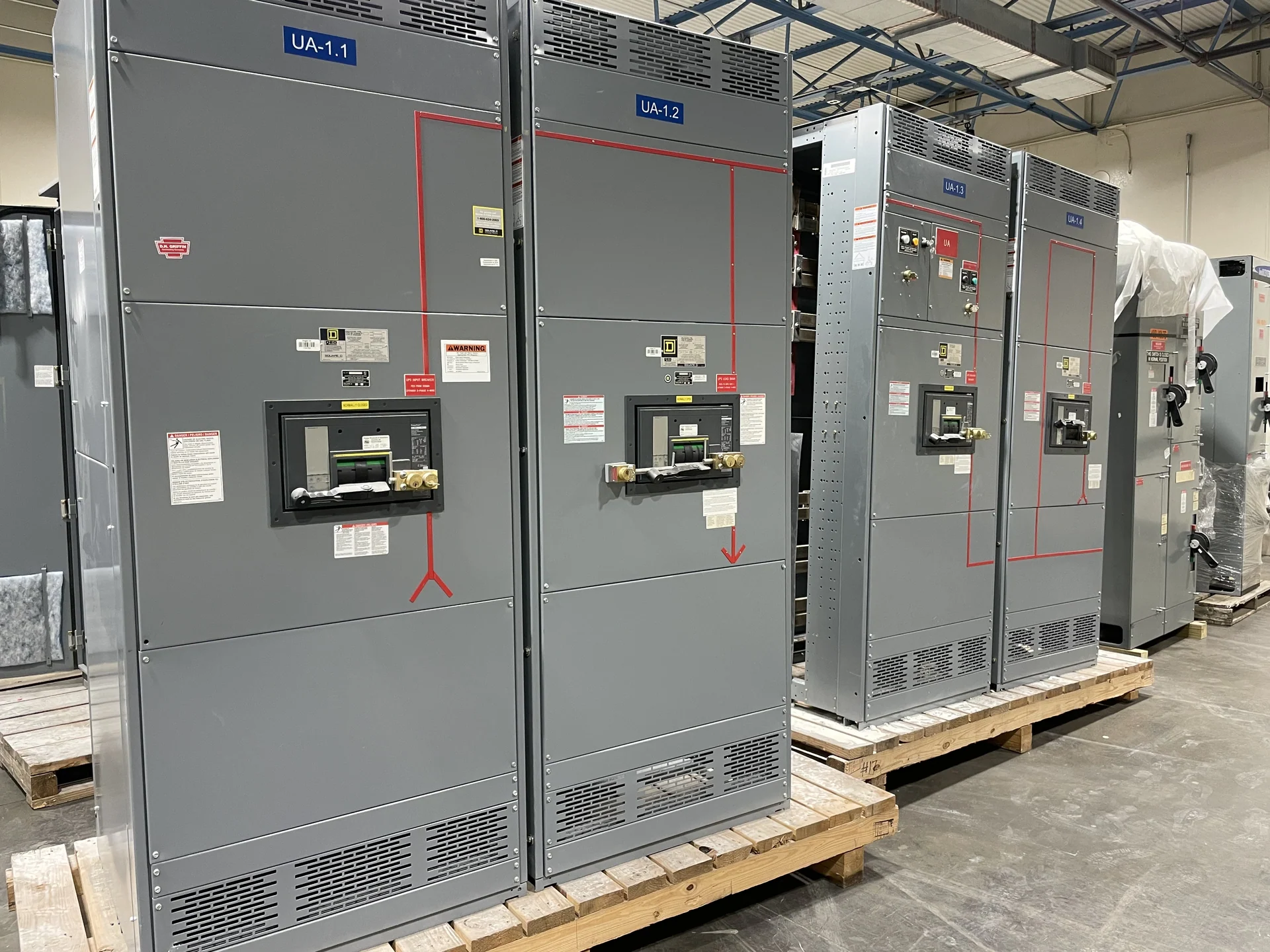
What Fused Metal-Enclosed Switchgear Does
Fused metal-enclosed switchgear combines enclosed switching equipment with fuses selected to interrupt defined fault conditions. The assembly can organize an incoming source, feeder circuits, or sectionalizing points while keeping energized power components inside a coordinated enclosure. The right arrangement depends on system voltage, continuous current, available fault current, grounding method, switching duty, and the operating sequence expected by the owner and electrical engineer. A manufacturer-built lineup is developed from those project inputs rather than from a generic equipment label.
Fuse Selection Starts with System Duty
Fuse selection is not simply a matter of matching a nominal ampere value to the connected load. The engineer must review the circuit's normal current, transformer or feeder characteristics, available fault current, voltage class, frequency, coordination objectives, and the fuse manufacturer's published characteristics. Time-current behavior affects how a fuse relates to upstream and downstream protective devices, while inrush or motor-starting conditions may influence the appropriate fuse family. For a custom build, provide the study inputs and desired coordination approach so the equipment scope can be reviewed coherently. Also identify whether the circuit is a transformer primary, motor feeder, capacitor-related circuit, or general distribution feeder, since those applications can present different transient and coordination questions. The final selection remains subject to engineering review and the applicable project requirements.
Enclosure and Switching Arrangement
The metal enclosure influences access, compartment arrangement, cable entry, clearances, ventilation, grounding, and the physical relationship between switches, fuses, bus conductors, and terminals. Indoor and outdoor installations can require different environmental and construction considerations, and an equipment room may impose limits on height, depth, door swing, lifting, or maintenance space. A practical layout review should identify line and load termination points, phase spacing, visible isolation needs, handle locations, interlocks, and the movement path from receiving area to final setting. These details affect both constructability and field installation effort, so early dimensional coordination can prevent conflicts with adjacent equipment, walls, trenches, and overhead routing. Confirm environmental assumptions, including moisture, dust, corrosion exposure, and temperature, before enclosure details are finalized.
Planning Fuse Replacement Access
Replacement access should be designed before fabrication, not left to an installation-day workaround. The project team should define how the circuit is isolated, what indication confirms the switching position, where fuses are reached, and what tools or handling method are acceptable under the facility's procedures. Consider door clearances, removable barriers, fuse dimensions, spare storage, labeling, and the space required for inspection. A qualified electrical professional must establish the safe work process; the manufacturer can use that interface information to coordinate enclosure details and documentation.
Custom Build and Project Documentation
Switchgear Builders manufactures new electrical switchgear in the United States, custom to project requirements, using American components and nationwide shipping for U.S. destinations. A useful inquiry can include the one-line diagram, system voltage and frequency, phase and wire arrangement, grounding method, continuous-current requirements, fault-duty information, fuse preferences, enclosure environment, dimensions, cable schedule, control voltage, metering needs, and operating sequence. Include installation constraints and document expectations as well, because drawings, nameplate data, wiring information, and test records must correspond to the final configuration.
Review Before Ordering
Before ordering fused metal-enclosed switchgear, compare the proposed bill of material and drawings against the protection study, utility or service requirements, installer access plan, and facility operating procedures. Confirm which party supplies fuses, cables, lugs, controls, metering, and field terminations, and identify every exclusion in the commercial quotation. If UL 891 may apply, treat applicability and any project-specific listing or verification as an item for confirmation during engineering review; it should not be assumed from the equipment name alone. Request pricing by sending the current electrical documents and the destination so shipping scope and project terms can be addressed accurately. The review should also reconcile phase identification, operating labels, spare-fuse provisions, grounding connections, and the responsibility for field verification. Clear responsibility at this stage reduces ambiguity when the assembly reaches the electrical room and installers prepare terminations.