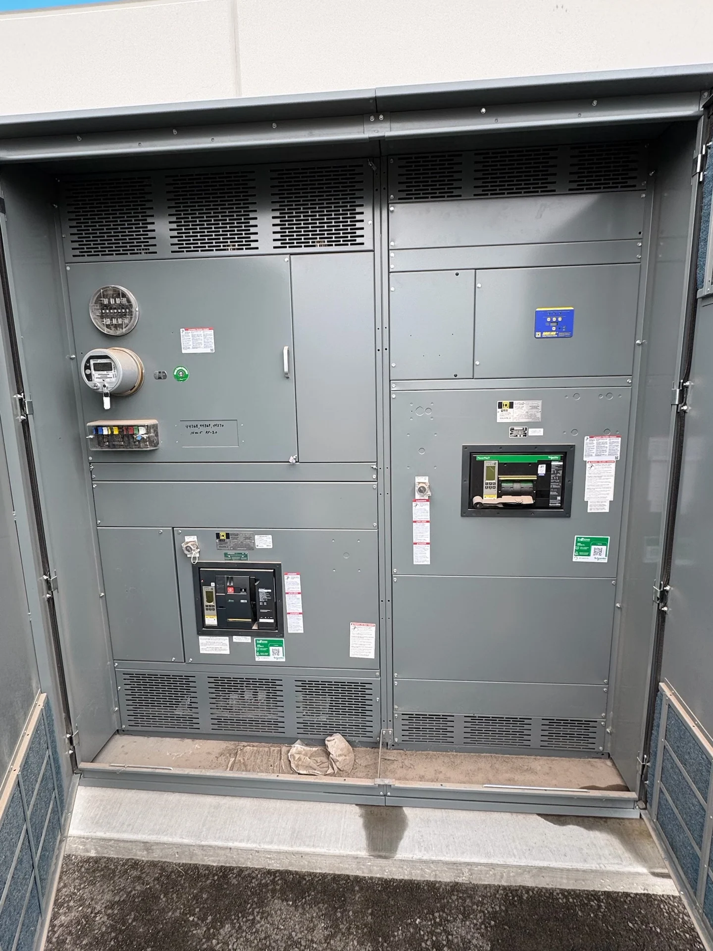
Switchgear Directs Electrical Power
Switchgear is an engineered assembly used to control and distribute electrical power between sources, buses, feeders, transformers, and connected loads. Its switching devices establish or interrupt a circuit under defined operating conditions, while bus conductors and enclosures organize the current path. A useful design begins with the one-line diagram, nominal voltage, phase arrangement, continuous current, available fault current, grounding method, and the operating sequence expected by the facility. Switchgear Builders manufactures new electrical switchgear in the United States, custom to project requirements, using American components and offering nationwide shipping.
Switching Supports Normal Operation
The switching function lets qualified personnel place feeders or sources in service, remove them from service, and change the distribution configuration when the project requires it. A main device can connect an incoming source to a bus; feeder devices can control separate circuits; and a tie device can connect bus sections when the operating plan permits. Main-tie-main arrangements, generator interfaces, and transfer schemes require clearly defined interlocks and sequences so that the equipment reflects the intended system behavior rather than merely fitting the available wall space. At the operating level, these choices determine whether a feeder remains energized, is transferred to another source, or is made available for maintenance. The sequence should account for normal switching, abnormal conditions, and restoration after an interruption, with each position and permissive represented in drawings. For example, an interlock may prevent a tie from closing until a source device is open, but the actual logic depends on the one-line diagram and protection study. Device labels, mimic diagrams, terminal points, and control-power sources should match the approved sequence so operators and installers can verify the intended behavior before energization.
Protection Limits Electrical Faults
Protection identifies abnormal current or other defined electrical conditions and commands an interrupting device to open the affected circuit. The protective device must be selected for its voltage class, continuous current, interrupting duty, and coordination with upstream and downstream equipment. Engineers commonly review available fault current, time-current characteristics, ground-fault requirements where applicable, and settings coordination before finalizing the lineup. The assembly itself also needs a project-defined short-circuit withstand or short-circuit current rating, as applicable; a product description alone cannot establish the correct rating for a particular system.
Isolation Creates a Defined Work Boundary
Isolation separates equipment or a circuit from an electrical source so an authorized work team can establish a controlled boundary for inspection, testing, or maintenance. Isolation is not the same as simply turning a control handle: the project may require visible disconnecting means, lockable positions, shutters, grounding provisions, stored-energy release, or interlocks appropriate to the equipment arrangement. The owner, engineer, and qualified electrical personnel should define the operating procedure, labels, access, and verification steps. Those requirements influence enclosure layout, device selection, control wiring, and documentation in a custom build.
Switchgear Connects with the Wider System
A switchgear lineup works as part of a larger distribution system, not as an isolated cabinet. Incoming utility or generator conductors, transformers, feeders, metering, protective relays, grounding conductors, control power, communications, and downstream equipment all create design interfaces. Physical details matter as well: cable entry, bus orientation, shipping splits, room clearances, maintenance access, lifting provisions, and the path from receiving to the electrical room can affect the final arrangement. Providing drawings, schedules, fault data, site conditions, and the intended sequence helps a manufacturer prepare a useful custom switchgear quote.
How to Define New Switchgear
When a project team is ready to buy new switchgear, it should request a design review rather than specify the word switchgear alone. Include the one-line diagram, system voltage and frequency, phase and wire configuration, grounding, current requirements, fault-duty study, enclosure environment, device types, metering, control voltage, interlocks, communications, dimensions, cable locations, documentation, inspection expectations, and shipping destination. If a specification references UL 891, confirm its applicability and any listing or capability for the specific project; it should not be assumed for every switchgear type. A U.S. manufacturer can then align the proposed assembly with the documented electrical and installation requirements.