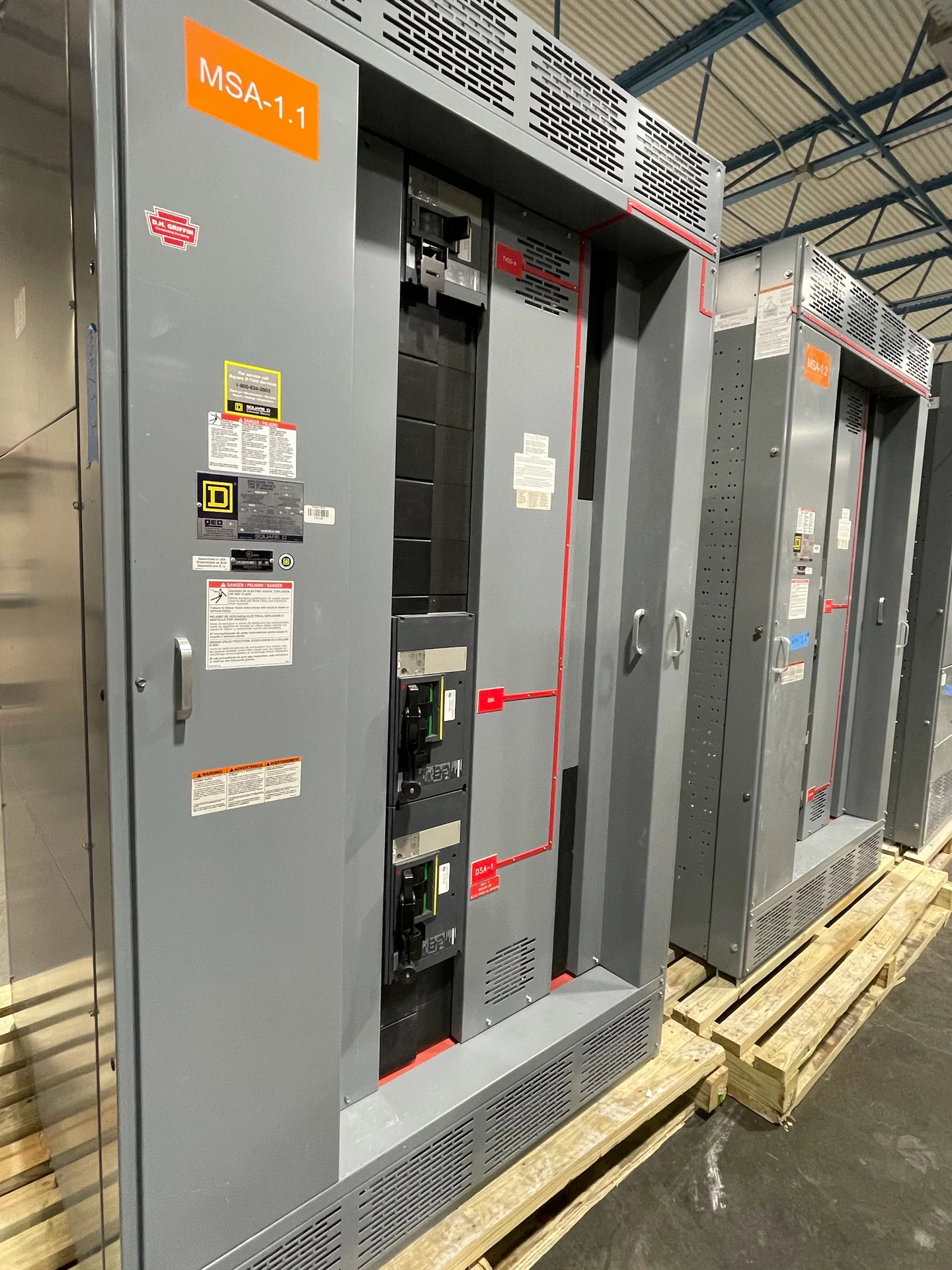
Service Entrance Definition
A service entrance is the part of an electrical distribution system where utility-supplied power connects to a facility's service equipment. In practical terms, the service entrance encompasses the incoming conductors, service disconnecting means, metering interface where applicable, grounding and bonding provisions, and the first equipment arranged to receive the utility supply. The exact boundary depends on the utility, adopted electrical requirements, and project design, so the phrase should be confirmed against the service drawings rather than treated as a universal physical dimension. The service point may be located at a property line, transformer, meter, or equipment connection, and responsibility for conductors and maintenance can change at that point. That is why a drawing should identify the utility demarcation explicitly instead of relying on the word service alone.
What the Service Entrance Connects
On one side of the service entrance is the utility connection, which may involve an overhead or underground service, utility-owned conductors, metering equipment, or a defined point of connection. On the other side is the facility distribution system, including the main protective device, bus, feeders, transformers, panelboards, or other equipment selected for the project. A service-entrance switchboard or switchgear lineup therefore has to match both sides: utility interface requirements and the facility's calculated loads, fault duty, voltage, phase, grounding arrangement, and operating plan.
Service Entrance Equipment Decisions
Designing new service entrance equipment starts with information that can be checked: nominal system voltage, frequency, phase and wire configuration, continuous load, available fault current, service conductor details, utility metering requirements, environmental conditions, enclosure location, and working-space constraints. The project team should also identify main-device type, feeder count, metering compartments, surge protection or monitoring needs, bus arrangement, cable-entry direction, and provisions for future circuits. These inputs let an American manufacturer build custom new switchgear to specification instead of guessing from a product label.
Service Entrance Versus Feeder Equipment
Service entrance equipment is not interchangeable with every piece of downstream distribution equipment. Service equipment is positioned at the utility-to-facility interface and may have distinct disconnecting, bonding, metering, marking, and utility-review requirements. A feeder switchboard farther inside the facility receives power from service equipment and distributes it to loads, but it is not automatically the service entrance. Clear one-line diagrams, equipment schedules, and responsibility boundaries help the engineer, utility, manufacturer, and installer coordinate the correct arrangement without conflating switchboards, switchgear, and panelboards.
Planning a New Service Entrance Lineup
A useful quote request should include the latest one-line diagram, service voltage, available fault current or utility study information, main and feeder ratings, physical dimensions, cable termination requirements, metering arrangement, enclosure environment, access direction, shipping destination, and required drawings or test records. It should identify whether the equipment is for a new facility, an expansion, or a planned replacement and explain the installation interfaces. Switchgear Builders manufactures new custom electrical switchgear in the United States, uses American components, and supplies equipment for nationwide shipping; project scope, applicability, and delivery details still require confirmation for the specific order.
Review Before Release and Installation
Before a service entrance design is released, the responsible engineer and utility should review the service point, metering, disconnecting means, grounding and bonding, fault-current basis, protective-device coordination, clearances, access, and cable routing. The manufacturer can use approved drawings and project requirements to coordinate the custom assembly, but the project team remains responsible for site conditions, installation, utility acceptance, and local requirements. If UL 891 is identified for a particular switchboard project, its applicability and any project-specific listing or verification must be confirmed rather than assumed.