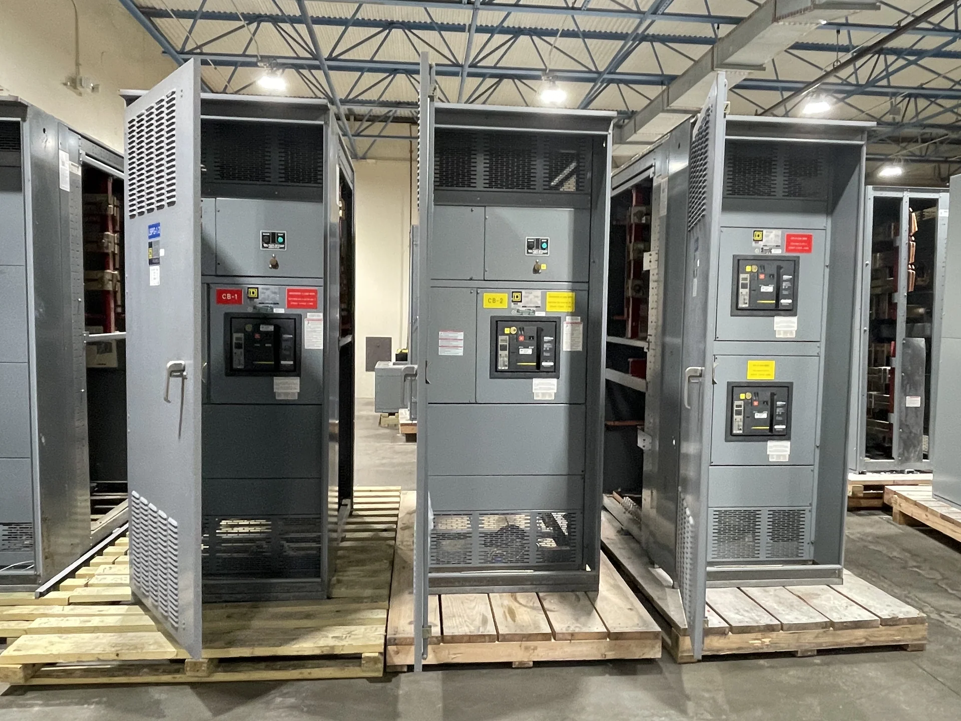
Two Ratings, Two Different Questions
Short-circuit rating versus interrupting rating is not a choice between two names for the same value. The assembly rating addresses whether the switchgear structure, bus system, supports, and connected construction can withstand or safely manage a specified fault duty under the applicable rating method. An interrupting rating addresses whether an individual circuit breaker or fuse can interrupt current at its terminals. A sound electrical distribution plan checks both levels and assigns each value to the correct piece of equipment. In practical terms, a device number on a schedule cannot substitute for an assembly value on the equipment specification. The distinction is especially important where several devices share a common bus or where a tie changes the energized fault path.
What an Assembly Short-Circuit Rating Describes
An assembly short-circuit current rating, or the applicable short-circuit withstand measure, relates to the lineup as an integrated construction rather than to one removable device alone. Engineers may need to review bus material, bracing, joints, enclosure construction, barriers, feeder compartments, grounding paths, and the specified duration or test basis. The rating must be evaluated against available fault current at the equipment location, with the system voltage and configuration clearly defined. A study may produce different available-current results for normal utility operation, alternate source operation, and a tie-closed condition. Those cases should not be blended into one unlabeled number. The selected equipment and devices must be checked for the operating states the design permits.
What an Interrupting Rating Describes
A protective device interrupting rating is the fault current the device is identified to interrupt under stated conditions, including the applicable voltage and current type. It does not automatically describe the withstand capability of the complete switchgear lineup. A breaker with an adequate interrupting rating can still be installed in an assembly whose bus, connections, or enclosure are not appropriate for the available duty. Device selection therefore belongs inside the broader equipment and system review. The device rating also should be read with its application conditions and any coordination assumptions. A feeder device may have a different duty from the main device, and a current-limiting arrangement can require careful review of how its characteristics relate to the assembly and downstream equipment.
How Engineers Compare the Values
Comparison begins with a fault-current study or other engineering determination of available current at each relevant bus and feeder location. The review should identify utility contribution, transformer impedance, generator or motor contribution where applicable, system grounding, conductor lengths, and operating configurations. Then compare the calculated duty with the assembly rating and with every protective device interrupting rating at its point of application. The governing design documents should state assumptions, margins, and any alternate source condition. This review is not merely a procurement exercise. It can affect room layout, bus segmentation, source interlocking, feeder routing, maintenance procedures, and the information provided to installers. A change in transformer size or source arrangement can require the ratings review to be revisited.
Implications for a Custom New Lineup
When Switchgear Builders manufactures new custom switchgear, the quote and design conversation should distinguish the desired assembly short-circuit capability from device interrupting requirements. Useful inputs include the one-line diagram, nominal voltage, phase and frequency, available fault current, main and feeder devices, bus arrangement, enclosure environment, dimensions, cable entry, control scheme, and documentation expectations. We manufacture in the United States, build to project specifications with American components, and coordinate nationwide shipping details around the approved equipment scope. A manufacturer can use those inputs to identify design questions before drawings are finalized, but the project engineer remains responsible for establishing the electrical duty and acceptance criteria. Clear responsibility prevents a quoted device rating from being mistaken for an engineering conclusion.
Documentation and Project Confirmation
Ask for a clear equipment schedule that identifies the assembly rating basis, device interrupting ratings, voltage conditions, and any assumptions requiring confirmation by the engineer of record or authority having jurisdiction. Drawings should make device positions, bus sections, ties, and source arrangements understandable, while test and inspection requirements should be agreed before fabrication. If UL 891 is relevant to a switchboard project, its applicability and any project-specific listing or capability must be confirmed for that project rather than assumed from a general description. Records should preserve the calculation revision, source assumptions, selected device data, and approved drawings so later changes can be evaluated against the same basis. This is useful when a project adds generation, changes transformers, or rearranges feeders after the original inquiry.