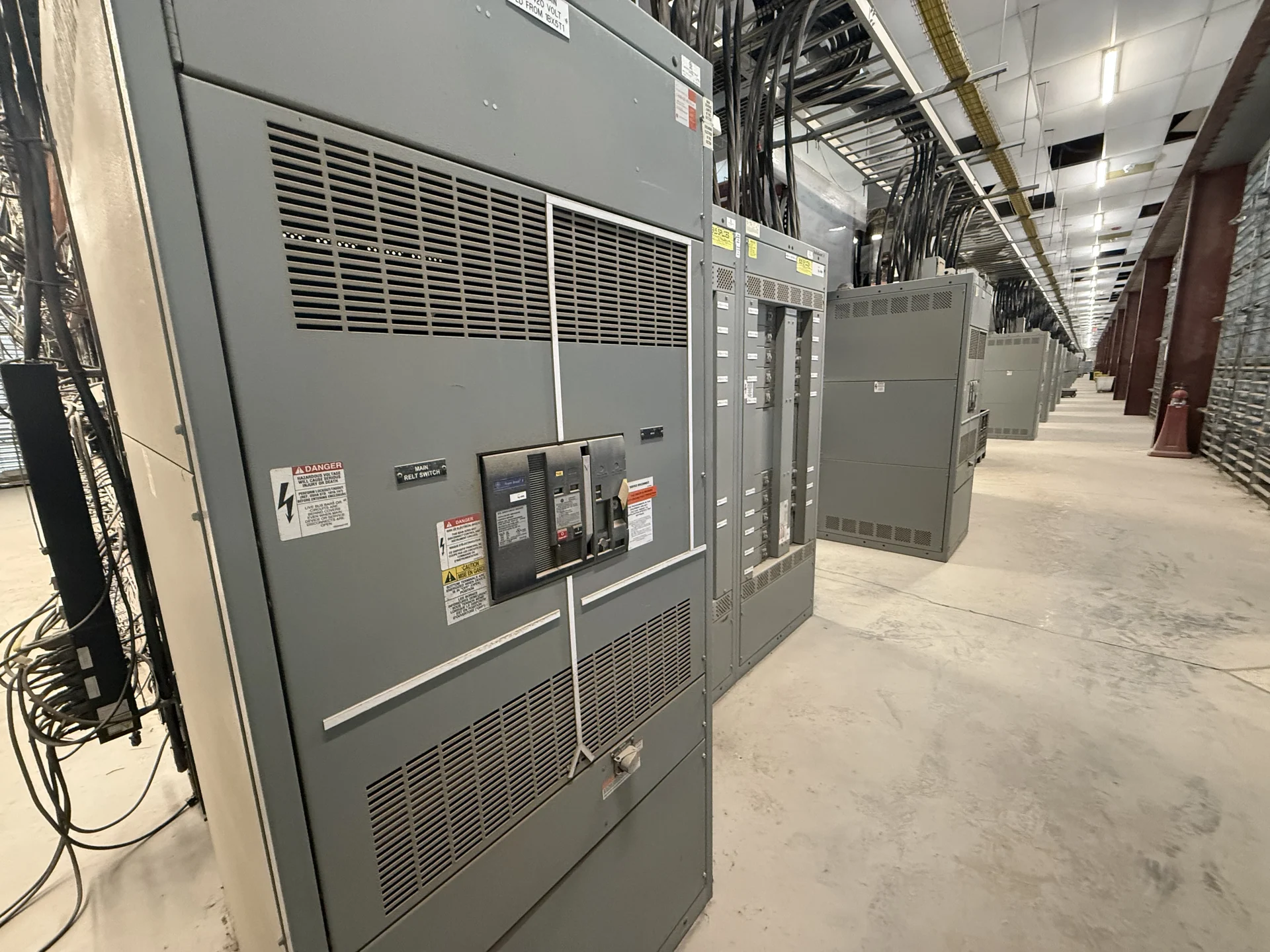
Start with the Campus Distribution Map
Medium-voltage distribution for university campuses begins with a clear map of sources, feeders, transformers, buildings, and future connection points. An engineer should identify the utility interface, nominal system voltage, phase arrangement, grounding method, available fault current, feeder lengths, and operating boundaries before equipment is selected. A campus may have a central substation, several building transformers, and multiple routing paths, but those are planning examples rather than assumptions about any particular university. The one-line diagram should show normal and alternate source paths, switching points, and the consequences of isolating each section.
Coordinate Feeder Switching and Protection
Feeder switching has to match the intended operating sequence, not simply the number of outgoing circuits. Define which devices open for maintenance, how a faulted feeder is isolated, whether a tie is normally open or closed, and who is authorized to operate each switching point. Protection studies should address available fault current, interrupting duties, time-current coordination, grounding, and relay inputs as applicable. For universities electrical distribution must also account for laboratories, residence halls, research loads, and other buildings with different continuity priorities; the manufacturer can build new custom equipment to the approved scheme, while the project engineer establishes settings and system coordination.
Treat Transformer Interfaces as Design Boundaries
The connection between medium-voltage switchgear and each transformer deserves its own review. Confirm transformer primary voltage, impedance, winding connection, grounding, secondary arrangement, inrush considerations, cable termination method, and protection requirements. Check whether the lineup needs a dedicated transformer feeder, primary fusing, a circuit breaker, metering, or provisions for a future transformer, because each choice affects compartment space, maintenance access, and coordination. Physical details matter as well: cable bend radius, entry direction, heat dissipation, clearances, lifting access, and the path from the receiving area to the electrical room should be documented before fabrication drawings are approved.
Plan for a Multi-Building Campus
A campus distribution system is often expanded in phases, so the initial lineup should be evaluated against the buildings and feeders that may be added later. Reserve capacity only when the electrical study, enclosure dimensions, bus arrangement, and protection concept support it; an empty space is not automatically a usable future feeder. Coordinate duct banks, manholes, cable schedules, transformer locations, building shutdown boundaries, and utility requirements with civil, structural, and installation teams. These interfaces help prevent a technically suitable switchgear application from becoming difficult to move, terminate, test, or maintain after delivery.
Define the New Equipment Package
A useful manufacturer inquiry should include the latest one-line diagram, equipment schedule, fault-duty information, floor plan, elevations, cable data, control voltage, metering needs, interlocks, communications requirements, environmental conditions, and documentation standards. Identify whether the equipment is indoor or outdoor, how sections will be shipped, and what receiving and rigging constraints apply. Switchgear Builders manufactures new electrical switchgear in the United States, builds custom to specification with American components, and can coordinate nationwide shipping; project-specific configuration, component details, manufacturing information, and shipment terms still need to be confirmed in the quotation and approved drawings.
Review Drawings, Tests, and Delivery Interfaces
Before release, compare the proposed arrangement with the campus one-line, protection study, room clearances, cable schedule, and installation responsibilities. Submittals should make device identification, phase labeling, grounding points, interlocks, terminal information, and shipping splits understandable to the installing team. Agree on inspection points, continuity and insulation checks, functional demonstrations, and the records required for the project rather than assuming a universal test package. If UL 891 is relevant to the assembly, confirm its applicability, construction requirements, and any project-specific listing or verification before the order is finalized; it should never be presumed from the equipment category alone.