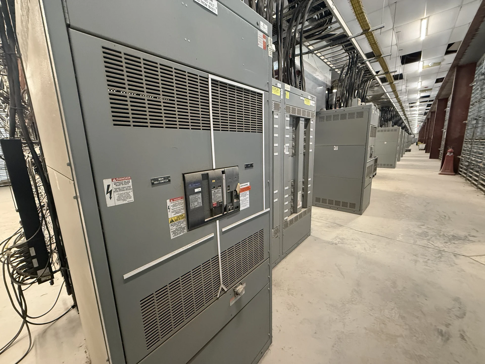
Start With the University Building’s Distribution Map
Electrical distribution for university buildings begins with a clear map of how power enters, branches, and reaches the building’s varied loads. A project team should identify the service voltage and phase arrangement, incoming source, main disconnecting equipment, feeder destinations, panelboard locations, emergency or alternate sources where applicable, and the relationship to campus distribution. Existing one-line diagrams, load schedules, fault-current information, utility requirements, room plans, and planned expansion should be reviewed together. This foundation helps a manufacturer develop new switchgear or associated distribution equipment that fits the building rather than treating a campus project as a generic commercial installation.
Coordinate Service Equipment With the Utility Interface
Service equipment for a university building must align with the utility interface, the building’s calculated demand, and the physical route from the service point to the electrical room. Confirm who supplies metering provisions, which disconnecting arrangement is expected, how grounding and bonding are addressed, and what available fault current applies at the service. The design should also account for working space, equipment access, cable bending, maintenance removal paths, and any phased construction constraint. Switchgear Builders manufactures custom new electrical switchgear in the United States, using American components and supplying equipment for nationwide shipping; project-specific utility and engineering requirements still govern the final arrangement.
Select Panelboards Around Real Loads and Future Work
Panelboards distribute branch circuits and smaller feeders, so their selection should follow the building’s actual load mix instead of an assumed room count. Separate schedules may be needed for lighting, receptacles, laboratory equipment, HVAC, information technology, food service, residence functions, and other specialized loads. Specify voltage, phase, circuit quantity, main-device needs, feeder protection, enclosure conditions, spare or future spaces, and the panel location relative to the served areas. Coordination with architectural plans matters because wall depth, access, fire-rated construction, and renovation sequencing can limit otherwise workable layouts.
Coordinate Feeder Protection Across the Campus
Feeder protection should be evaluated from the building main through distribution feeders and panelboard mains to downstream branch devices. The engineer can use available fault current, conductor ampacity, equipment ratings, time-current characteristics, grounding details, and operating priorities to review selectivity and clearing behavior where required by the project. Campus ties, adjacent buildings, generators, transfer equipment, and large motor loads may change the study inputs. Provide the manufacturer with the latest one-line diagram and protection schedule, then resolve device settings, trip-unit data, metering, and control interfaces before drawings are finalized.
Design for Occupied-Campus Installation Constraints
University construction often involves occupied buildings, restricted delivery routes, academic calendars, research spaces, and multiple stakeholders. A practical equipment package therefore includes verified dimensions, shipping splits if needed, weights, lifting points, doorway and elevator limits, storage responsibility, and the planned movement path into the electrical room. The installation team should coordinate shutdowns, temporary power, cable termination access, labeling, and commissioning responsibilities with campus facilities and the electrical contractor. Nationwide shipping can be planned around the destination and freight requirements, but transit timing and project feasibility must be confirmed for the specific order.
Prepare a Complete New-Equipment Inquiry
A useful inquiry for university building switchgear applications should include the project location, building type, one-line diagram, nominal voltage, frequency, phase and wire configuration, grounding method, continuous-current requirements, available fault current, feeder list, protective-device preferences, enclosure environment, dimensions, cable-entry direction, metering, controls, documentation, and testing expectations. Include campus standards and the responsible engineer’s review criteria, while identifying assumptions that remain open. Switchgear Builders can use that information to develop a custom manufacturer quotation for new electrical switchgear; the purchaser should compare scope, drawings, component details, shipping terms, and exclusions rather than relying on a generic equipment description.