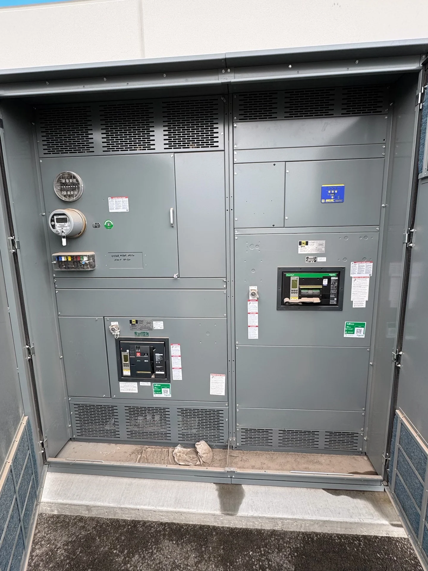
Start With the Alaska Feeder Design Basis
Planning Alaska switchgear for an industrial facility begins with a clear electrical basis rather than a location label alone. Identify the nominal and maximum system voltage, phase arrangement, frequency, grounding method, continuous feeder current, available fault current, and the loads served by each lineup. A medium-voltage switchgear inquiry should also show whether feeders supply transformers, motors, process equipment, or multiple buildings. Switchgear Builders manufactures new custom electrical switchgear in the United States, using American components and coordinating the build around the project's documented requirements. Record assumptions separately from confirmed inputs, especially where utility information or an expansion phase remains pending. That distinction helps the design team identify decisions that can change the lineup before drawings are approved.
Coordinate Voltage Class and Transformer Connections
Transformer connections deserve early attention because the primary switching arrangement, secondary distribution, grounding, and protection are interdependent. Provide transformer kVA, primary and secondary voltages, impedance when available, connection details, neutral treatment, and the intended feeder path. Confirm whether the lineup needs incoming switching, transformer feeder protection, sectionalizing, or a defined main-and-tie sequence. The equipment voltage class must match the system and insulation requirements; nominal voltage by itself is not enough to select a suitable medium-voltage assembly.
Develop Protection and Relay Inputs
Protective relaying should be developed from the complete distribution study, not selected as an isolated switchgear feature. Gather utility data, transformer information, generator or inverter sources where applicable, feeder conductor details, motor contribution assumptions, grounding information, and time-current coordination objectives. Specify relay functions, sensing arrangements, trip logic, communications, event records, and control power only after the electrical engineer defines the operating philosophy. A manufacturer can then translate approved relay and interlock requirements into drawings, wiring, device placement, and a test plan.
Check Fault Duty and Physical Conditions
Fault duty must be checked at each relevant bus and feeder, including the effect of transformer impedance, parallel sources, motors, and future system changes. Compare calculated available fault current with the applicable interrupting, withstand, bus bracing, and protection requirements for the selected equipment. Alaska projects may also require careful review of enclosure exposure, condensation control, indoor room conditions, cable entry, seismic design criteria, access routes, and foundation interfaces. These conditions belong in the project specification so the final configuration is engineered for its actual installation environment. Ask the engineer to identify the calculation date and source assumptions, because a later utility change or added generation can alter the duty at a bus. Equipment selection should follow the approved study and project specifications.
Plan Drawings, Interfaces, and Field Work
A useful custom switchgear package depends on coordinated information from the owner, consulting engineer, electrical contractor, transformer supplier, utility, and qualified installation team. Include the latest one-line diagram, equipment schedules, protection study assumptions, room dimensions, cable sizes and entry direction, control schematics, communications points, lifting limits, shipping splits, and required submittal documents. Review working clearances, maintenance access, arc-flash study interfaces, grounding conductors, and termination space before fabrication. This process reduces late changes without assuming that one standard lineup fits every facility.
Coordinate Nationwide Delivery for the Project
For an Alaska project, shipping and receiving details should be part of the equipment conversation from the beginning. Provide the destination, site access limitations, receiving hours, unloading equipment, route constraints known to the project team, preferred shipping sections, and the responsibilities of the freight carrier, rigging contractor, and installer. Switchgear Builders supplies new manufacturer-built equipment with nationwide shipping coordination; project-specific service, packaging, freight terms, and delivery estimates must be confirmed for the actual order. Final field installation, cable termination, testing, and energization remain coordinated with qualified project personnel. Confirm whether the site requires staged delivery, weather-protected storage, or a specific handoff sequence. Those details affect packaging and coordination even when the electrical design itself remains unchanged.