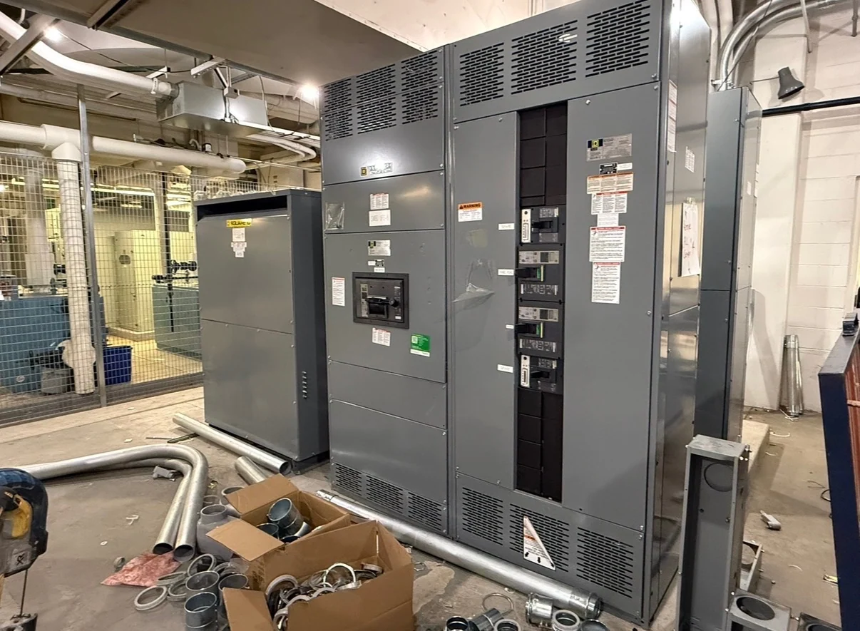
Plan the California Water-Treatment Application First
California switchgear planning for a treatment plant begins with the process duty, not a catalog label. Pumps may serve raw-water intake, filtration, chemical handling, sludge management, or discharge, and each duty can impose different starting, sequencing, and continuity needs. A project team should identify every motor, horsepower, voltage, phase, full-load current, starting method, operating profile, standby relationship, and criticality. Motor control centers for water treatment pumps and process equipment can then be organized around the plant one-line diagram, feeder protection, available fault current, and space limits. Switchgear Builders manufactures new custom electrical equipment in the United States, using American components and shipping nationwide, including to California projects; final configuration remains subject to engineering review.
Choose Motor Starting Around Process Behavior
Motor starting is a system decision because an across-the-line starter, reduced-voltage method, or variable frequency drive affects inrush, acceleration, mechanical stress, controls, and upstream voltage performance. A pump that starts against a controlled process condition may have different requirements from one that must accelerate a high-inertia assembly or operate through frequent cycles. The equipment specification should state starting current assumptions, acceleration expectations, bypass needs, overload strategy, isolation requirements, and whether simultaneous starts are permitted. Reviewing these points with the electrical engineer and pump supplier helps prevent a motor control center layout that fits physically but does not match the treatment sequence or distribution study.
Evaluate Drives, Harmonics, and Heat
Variable frequency drives can provide valuable speed control for changing flow or pressure, but they introduce design questions beyond simply reserving a bucket. The project should define drive input and output ratings, motor cable distances, bypass philosophy, control references, communications, fault indications, and maintenance access. Drive heat losses also influence enclosure ventilation and room heat calculations, while harmonics may require evaluation at the distribution-system level. Where a process needs fixed-speed operation during a drive outage, the electrical design should document the intended transfer or bypass sequence rather than assuming one. A custom builder can coordinate drive compartments, lineups, wiring, and terminals after those engineering inputs are established.
Account for California Site Conditions
Environmental conditions should be translated into equipment requirements instead of treated as a generic location label. Identify whether the motor control center will be indoors, in a conditioned electrical room, or exposed to moisture, washdown, dust, corrosive chemicals, salt air, temperature variation, or elevation. The design team should also document enclosure type, ventilation, condensation control, cable-entry direction, housekeeping pad dimensions, seismic anchorage criteria where applicable, and access for installation and maintenance. These conditions can change materials, coatings, clearances, and component arrangements. California electrical distribution projects should confirm applicable local requirements and utility or authority interfaces with the responsible engineer before drawings are finalized.
Coordinate Controls and Operating Sequences
Water and wastewater controls often connect pump starters or drives to level instruments, flow measurement, valves, analyzers, remote I/O, alarms, and supervisory systems. A useful control narrative should identify permissives, interlocks, lead-lag rotation, duty and standby selection, local and remote modes, fail states, restart behavior, emergency stops, and operator indications. The motor control center drawing package should show terminal assignments, wire numbering, control power, communication interfaces, and separation between power and control circuits as required by the project. Clear sequence documentation gives the manufacturer and integrator a common basis for panel layout and helps installers verify field connections without guessing at process intent.
Prepare a Complete Manufacturer Inquiry
For a California project inquiry, provide the one-line diagram, motor schedule, load list, fault-current information, site conditions, enclosure requirements, physical footprint, cable-entry preferences, control schematics, network details, desired accessories, drawing standards, inspection expectations, and shipping destination. Also identify whether the lineup is part of a new plant, an expansion, or a replacement interface, because that affects field dimensions and outage coordination. Switchgear Builders can review the defined scope for a new custom build and coordinate nationwide shipping details such as shipping splits, lifting provisions, packaging, receiving access, and freight responsibilities. Any service scope, delivery estimate, and UL 891 applicability must be confirmed for the specific project rather than assumed from the location.