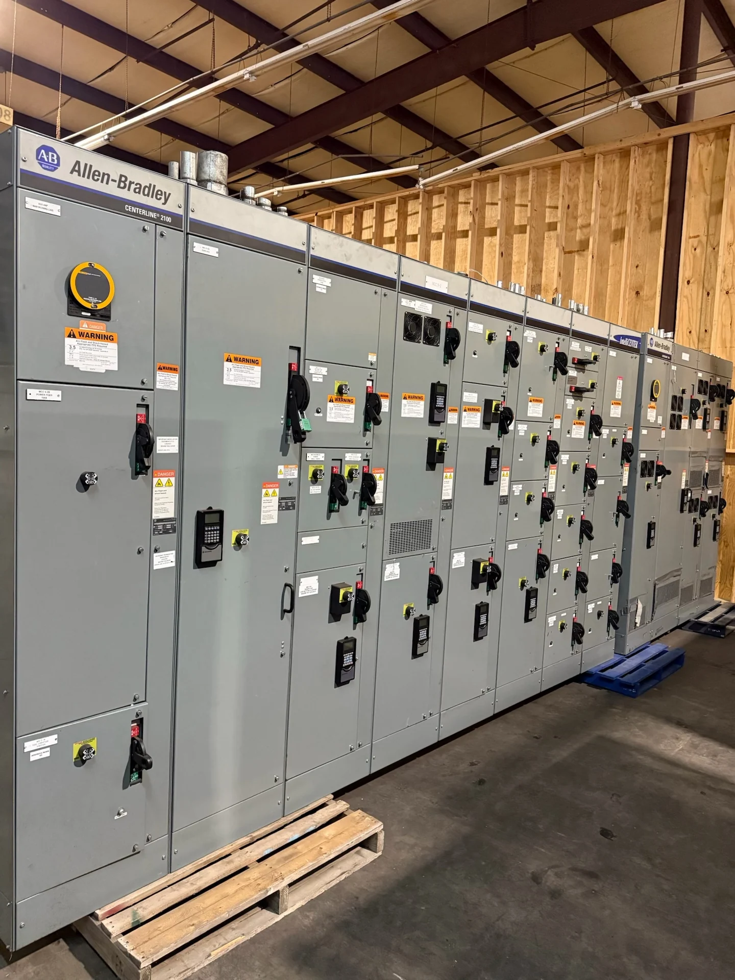
Start with the San Francisco Data Center Electrical Basis
A data center distribution switchgear inquiry for San Francisco, California should begin with the electrical basis of design, not a catalog label. Identify utility service characteristics, nominal voltage, phase and frequency, grounding method, calculated loads, short-circuit duty, environmental exposure, and the physical route into the electrical room. Then map each source, main device, tie, feeder, transformer, UPS interface, generator connection, and critical load. This information lets an American manufacturer develop new switchgear custom to spec, with American components and nationwide shipping for the project. It also gives the engineer and contractor a common reference for reviewing dimensions, interfaces, documentation, and installation responsibilities before a quote is compared.
Define Redundancy as an Operating Sequence
Redundancy is more useful when expressed as a sequence of permitted states rather than a simple count of sources. The project team should define normal source operation, transfer conditions, maintenance bypasses, bus-tie positions, source paralleling or isolation rules, and the response to a failed feeder or generator. For data center distribution switchgear, document whether independent power paths must remain physically and electrically separated, how interlocks prevent an unsafe operating combination, and which loads may be shed. A custom switchgear builder can use those decisions to coordinate mains, ties, protective devices, controls, status points, and nameplate information without assuming that every facility requires the same topology.
Plan Maintainability Around Real Access Constraints
Maintenance access should be evaluated alongside reliability goals, because a lineup that fits on a drawing may be difficult to service in the finished building. Confirm working clearances, door swing, cable bending space, lifting and removal paths, overhead obstructions, arc-flash boundaries established by the project analysis, and the separation needed for independent distribution paths. Discuss drawout or fixed device arrangements, test positions where applicable, control-power sources, shutters or barriers when specified, and provisions for identifying circuits. For a San Francisco project, the equipment package should also reflect the responsible engineer's seismic, building, access, and installation requirements rather than assuming a generic room layout.
Coordinate Generator and Backup Source Interfaces
Generator interfaces require more than a feeder connection. The one-line and control narrative should identify generator voltage, grounding, breaker functions, sensing points, start and transfer signals, synchronization requirements if applicable, load-shed priorities, emergency operating modes, and the relationship between automatic transfer equipment and switchgear mains or ties. Confirm whether the design permits closed transition, open transition, or another project-defined sequence, and identify who supplies relays, controls, communications, and programming. A manufacturer can then build new equipment around the documented interface, while the engineer verifies source compatibility, fault duty, selective coordination, and the responsibilities of the generator, transfer, and distribution packages.
Review Protection and Data Before Fabrication
Protective coordination should be developed from the distribution study and reflected in the equipment specification. Provide available fault current at each relevant bus, transformer data, conductor information, breaker or fuse characteristics, ground-fault requirements, relay functions, intended settings, and coordination objectives. Separate interrupting duty, short-circuit withstand, continuous current, and voltage class so each device and the assembly are evaluated for the correct responsibility. If arc-flash mitigation or energy-reduction features are part of the design, define the desired operating behavior and study assumptions without treating them as a blanket performance claim. Before fabrication, reconcile the approved one-line, elementary diagrams, device schedule, terminal plan, and physical arrangement.
Prepare a Manufacturer-Ready Quote Package
A useful request for San Francisco California switchgear should include the latest one-line diagram, load schedule, source and generator information, fault study inputs, protective-device schedule, control narrative, enclosure environment, dimensions or room drawings, cable entry preferences, shipping destination, lifting limits, and required submittal and test records. State which items are mandatory and which remain open for engineering review. Switchgear Builders manufactures and supplies new electrical switchgear in the United States, custom to spec, using American components and offering nationwide shipping; project-specific applicability of UL 891, any requested listing, and all other standards must be confirmed for the particular assembly. This disciplined package makes scope, exclusions, approvals, and delivery coordination easier to evaluate.